
Charging inlet

Active Publication Date: 2020-07-30
SUMITOMO WIRING SYST LTD
View PDF0 Cites 0 Cited by
  • Summary
  • Abstract
  • Description
  • Claims
  • Application Information

AI Technical Summary

Benefits of technology

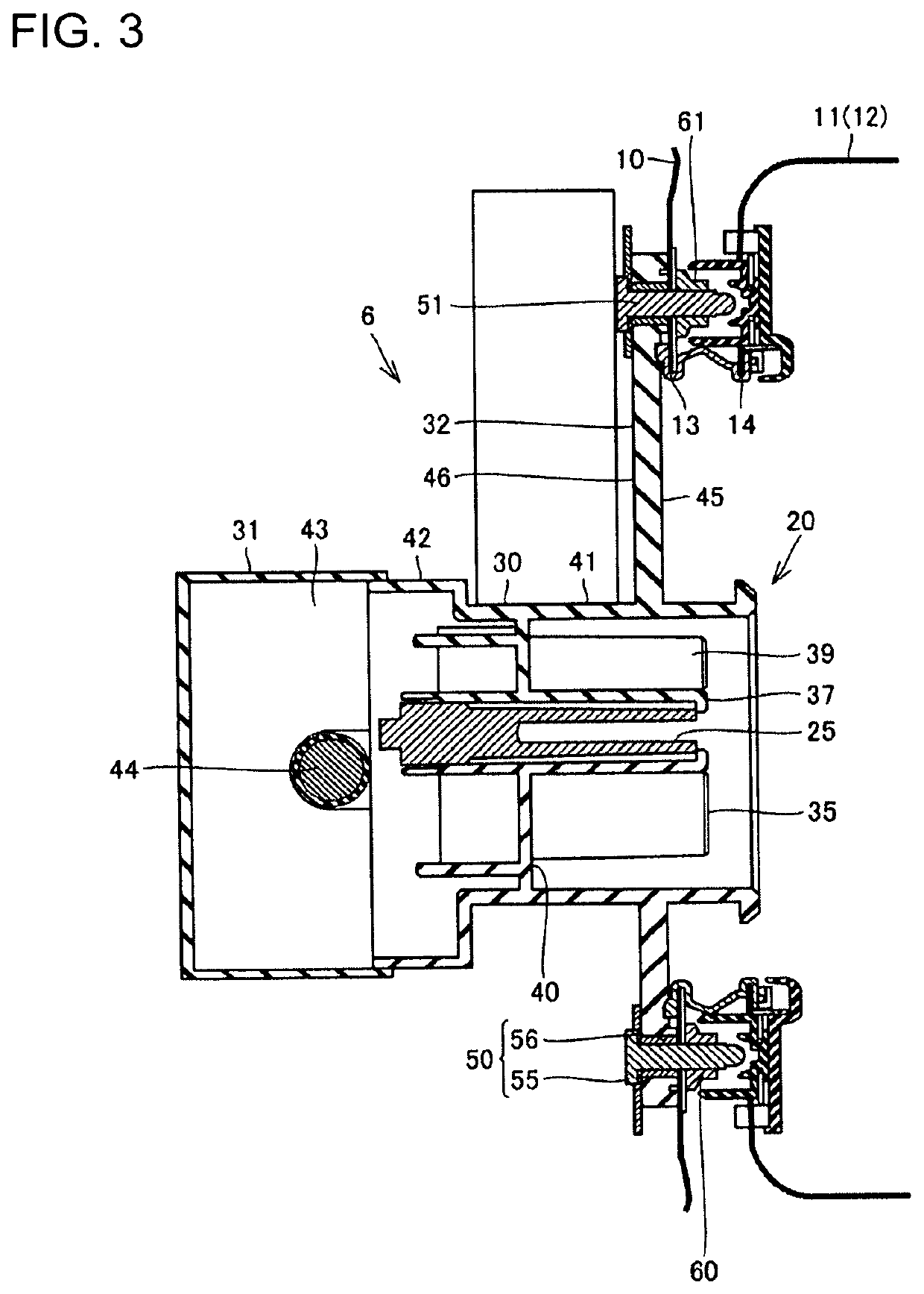
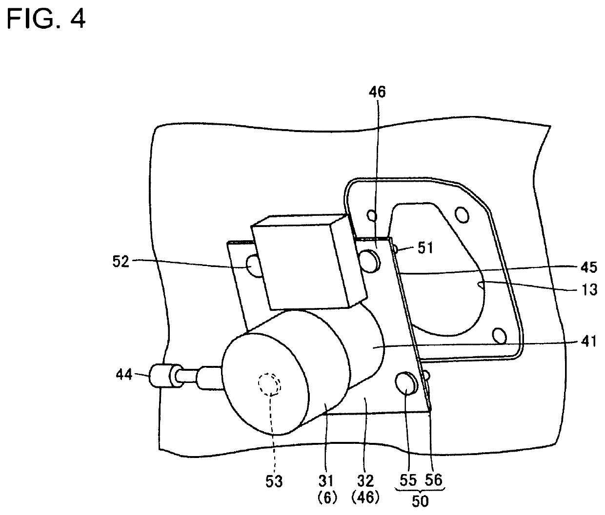
The present disclosure describes a charging inlet that can be easily fixed to a vehicle body. The invention includes a housing with terminals inside, a mounting plate that is attached to the vehicle body, and a bolt that is inserted into two through holes in the vehicle body and the mounting plate. A nut is then tightly engaged with the bolt, securing the charging inlet to the vehicle body. This configuration makes it simple to install the charging inlet, even when cables are connected to it.

Problems solved by technology

In the process of fixing the charging inlet to the body in this way, a step of inserting the connection cables requires time and effort.

Method used


Image

  • Charging inlet
  • Charging inlet
  • Charging inlet

Examples


Embodiment Construction

[0023]A charging inlet according to an embodiment is illustrated in FIGS. 1 to 5 where the same or substantially same components are denoted by the same reference signs. Not that, the components described below may be followed by the components as claimed written in parenthesis.

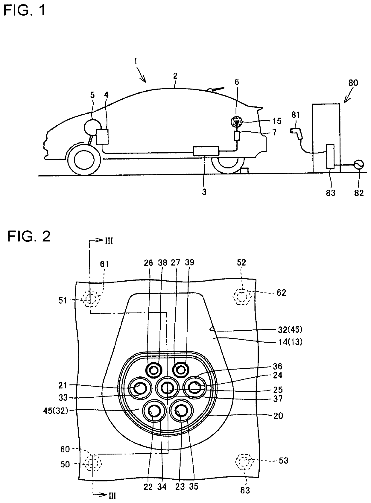
[0024]FIG. 1 is a diagram schematically showing a vehicle 1. The vehicle 1 includes a body 2, a battery 3, a PCU 4, a motor generator 5, a charging inlet 6 and a charger 7.

[0025]The battery 3 is a secondary battery and, for example, a lithium ion battery. The PCU 4 includes an inverter and a converter. The PCU 4 converts direct-current power supplied from the battery 3 into alternating-current power and supplies the converted power to the motor generator 5. The motor generator 5 is driven by the alternating-current power supplied from the PCU 4 to drive drive wheels.

[0026]The body 2 includes an inner body and outer panel components. The inner body is, for example, a monocoque body. The outer panel components ...


PUM


Abstract

It is aimed to provide a charging inlet easily mountable on a body of a vehicle. A charging inlet is fixed to a vehicle body (10) and includes a housing main body (30) having a plurality of terminals accommodated inside, a mounting plate provided on an outer peripheral surface of the housing main body and arranged on an inner surface side of the vehicle body (10), bolts (50) inserted into first through holes formed in the mounting plate and second through holes formed in the vehicle body (10), and nuts (60) provided on an outer surface side of the vehicle body (10) and threadably engaged with the bolts (50).

Description

BACKGROUNDField of the Invention[0001]This disclosure relates to a charging inlet.Related Art[0002]Plug-in vehicles capable of charging a battery with power from an external power supply have attracted attention in recent years. A plug-in vehicle includes a charging inlet provided on an outer surface of the vehicle. The charging inlet is connectable to a charging plug provided outside.[0003]The charging inlet includes an inlet housing, a connector fitting portion, power terminals and communication terminals.[0004]The inlet housing includes a mounting plate, a tubular portion formed on the front surface of the mounting plate and an annular fitting wall formed on the back surface of the mounting plate. The mounting plate is formed with bolt holes along an outer periphery thereof.[0005]The tubular portion projects out of the vehicle from the front surface of the mounting plate. Additionally, the tubular portion is hollow and is formed with a through hole. The through hole is extends fr...

Claims


Application Information

Patent Timeline
IPC IPC(8): H01R13/74H02J7/00B60L53/16
CPCB60L53/16H01R13/748H01R2201/26H02J7/0045B60K1/00
Inventor KARASAWA, MASAHIROHASHIMOTO, HIRONOBUMATSUDA, TOSHIYUKI
Owner SUMITOMO WIRING SYST LTD
Learn More