Hearing device with locking system for connectors

Inactive Publication Date: 2007-08-09
SONOVA AG
View PDF5 Cites 0 Cited by
  • Summary
  • Abstract
  • Description
  • Claims
  • Application Information

AI Technical Summary

Benefits of technology

[0012] To prevent the first fastener to be pulled out of said second component, a swiveling individual locking element is provided to securely lock said first fastener within said second component. By providing said locking element at the second component, the first fastener arranged at one end of the connecting means may be easily fixed and on demand later on detached from said second component of the hearing device. Thus, an easy disconnection of the second component from the connecting means and therefore from the first component of the hearing device may be performed and a quick and easy replacement of the first component or eventually of the second component may be accomplished.
[0013] In a further embodiment, an opening is arranged at the second component for receiving at least a part of said first fastener, wherein at least one recess is arranged at the sidewall of said opening providing said retaining or locking surfaces for said individual locking element. The recess will receive the respective ends of the locking element, when the locking element is turned or swiveled into its locking position. Therefore, the recess is arranged at the sidewall of said opening, with

Problems solved by technology

Although the ITC and especially CIC hearing devices are preferred by many users due to their low visibility from outside, their drawbacks of limited maximum amplification, limited battery lifetime, limited receiver quality and not suitable space within the ear canal, BTE hearing devices are still demanded and will still be used in the future.
The use of the resilient snap-in tongues allows an easy assembling of the fastener, but is only suitable if the shell of the CIC-component includes a soft ear mold, that may be squeezed to loosen the tongues for a non-destructively disassembling of the fastener and therefore of the connector.
Such a fastening means is not suitable in case of rigid shells, as the fasteners may not be disasse

Method used


Image

  • Hearing device with locking system for connectors
  • Hearing device with locking system for connectors
  • Hearing device with locking system for connectors

Examples


Embodiment Construction

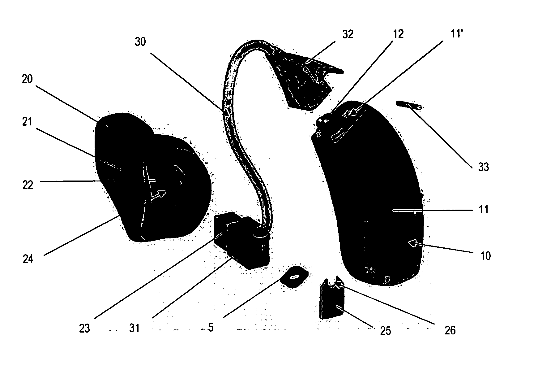
[0038] Referring to FIG. 1, a first embodiment of a hearing device according to the present invention is shown in its partly disassembled state. The hearing device comprises a BTE-device 10 (behind-the-ear) as a first component, an ITE-device 20 (in-the-ear) as a second component and a tube 30 as connecting means between the BTE-device and the ITE-device.

[0039] The BTE-device 10 has a housing 11 adapted to be worn behind the ear by the user and containing common electronic modules, such as a sound processing circuitry, microphone and battery.

[0040] The ITE-device 20 has a housing 21 adapted to be inserted into the outer part of the ear canal. The shape of housing 21 in this example is individually shaped to fit exactly into the ear shell and / or ear canal of an individual person. This is done by applying an individual fitting process by a specialized fitter. A faceplate 22 is arranged at the back end of housing 21, to receive the active components of ITE-device 20 as well as tube 3...


PUM


Abstract

The present invention provides a hearing device with locking apparatus comprising a first component (10) with a housing (11) being adapted to be carried outside of or at the human body, a second component (20) to be inserted either partially or fully into an ear canal of a human body and connecting means connecting mechanically said first and said second component (10;20). The connecting means comprise a tube (30) and a first fastener (31) being arranged at one end of said tube (30) and being adapted to detachably connect said second component (20) with said connecting means. The first fastener (31) further comprises an individual locking element (5;9) to be swiveled into retaining or locking surfaces (24′) arranged within said second component (20), thereby contacting outer surfaces of said first fastener (31) in its connected state with said second component (20). The first fastener (31) thus will be detachably secured to the second component (20) of the hearing device.

Description

TECHNICAL FIELD [0001] This invention relates generally to hearing devices, hearing instruments or hearing aids and particularly to hearing devices with at least a first component to be arranged outside the ear or the ear canal respectively and a second component to be arranged in the ear or ear canal respectively, communicatively connected to each other by connecting means. BACKGROUND OF THE INVENTION [0002] State of the art hearing devices are commonly either behind-the-ear (BTE) hearing devices, in-the-ear (ITE) hearing devices, in-the-canal (ITC) hearing devices or completely-in-the-canal (CIC) hearing devices. BTE hearing devices comprise sound conduction tubes to transmit the amplified sound from the BTE hearing device arranged behind the ear into the user's ear canal. The other hearing devices, ITE, ITC and CIC, are already arranged at or in the ear canal and thus have only short sound conduction tubes or no tubes at all. [0003] Although the ITC and especially CIC hearing dev...

Claims


Application Information

Patent Timeline
IPC IPC(8): H04R25/00
CPCH04R25/60H04R25/604H04R25/608H04R2225/63H04R25/652H04R2225/021H04R25/65H04R2225/0213H04R2225/57H04R25/607H04R25/609H04R2225/0216
Inventor OCHSENBEIN, ANDRE LUCIEN
Owner SONOVA AG
Why Eureka
Try Eureka