Lifting and leveling assembly for precast concrete slabs and method

a technology of precast concrete and assembly, which is applied in the direction of transportation and packaging, roads, highway maintenance, etc., can solve the problems of tripping hazards, increased the likelihood of misplaced parts during installation, and cost-consuming leveling techniques

Active Publication Date: 2016-05-24
FRANCIES III SIDNEY E
View PDF27 Cites 44 Cited by
  • Summary
  • Abstract
  • Description
  • Claims
  • Application Information

AI Technical Summary

Benefits of technology

[0016]Rotating the exposed bolt head of the threaded lifting bolt in a first direction positions the bolt head above the top surface of the precast concrete slab to accommodate the attachment of a lifting device. Rotating the exposed bolt head of the threaded lifting bolt in a second direction positions the bolt head beneath the top surface of the concrete slab and raises the level of the precast concrete slab.

Problems solved by technology

The slabs are leveled using precise surveys and excavation, plastic leveling shims, grout leveling pads or a process known as “mud jacking”; however, these leveling techniques can be costly and time consuming.
The lifting and leveling device presents problems during installation and use, including that the threaded end cap and separate threaded bolt increases the likelihood of misplaced parts during installation.
Also, the threaded bolt is always disposed above the surface of the concrete slabs during lifting and leveling, presenting tripping hazards.
The lifting and leveling device also requires removing the end cap, inserting the threaded bolt and lifting device and then subsequently removing the threaded bolt and lifting during casting, lifting, leveling and grouting, which adds significant time to the construction or repair of concrete surfaces using precast concrete slabs.
Furthermore, filling the threaded sleeve with grout or cement prevents subsequent use of the leveling lift device.

Method used


Image

  • Lifting and leveling assembly for precast concrete slabs and method
  • Lifting and leveling assembly for precast concrete slabs and method
  • Lifting and leveling assembly for precast concrete slabs and method

Examples


Embodiment Construction

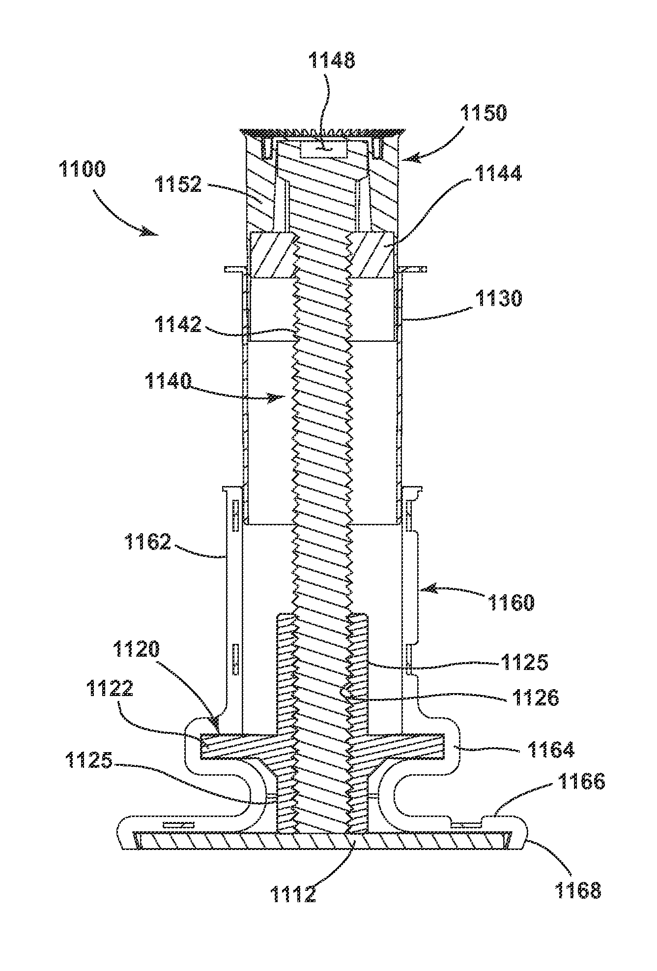
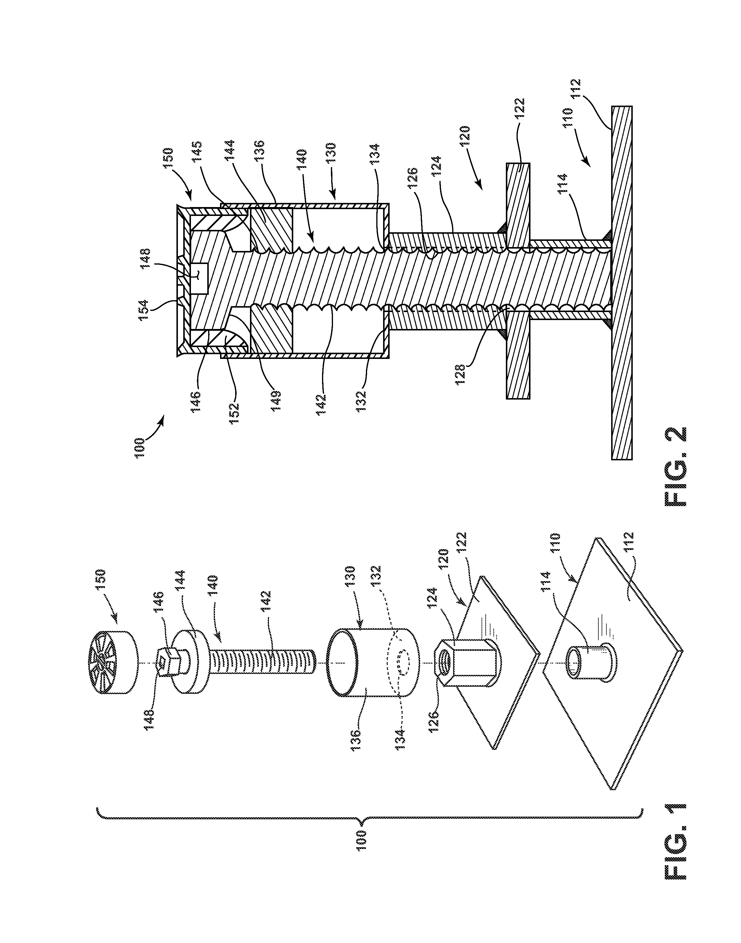
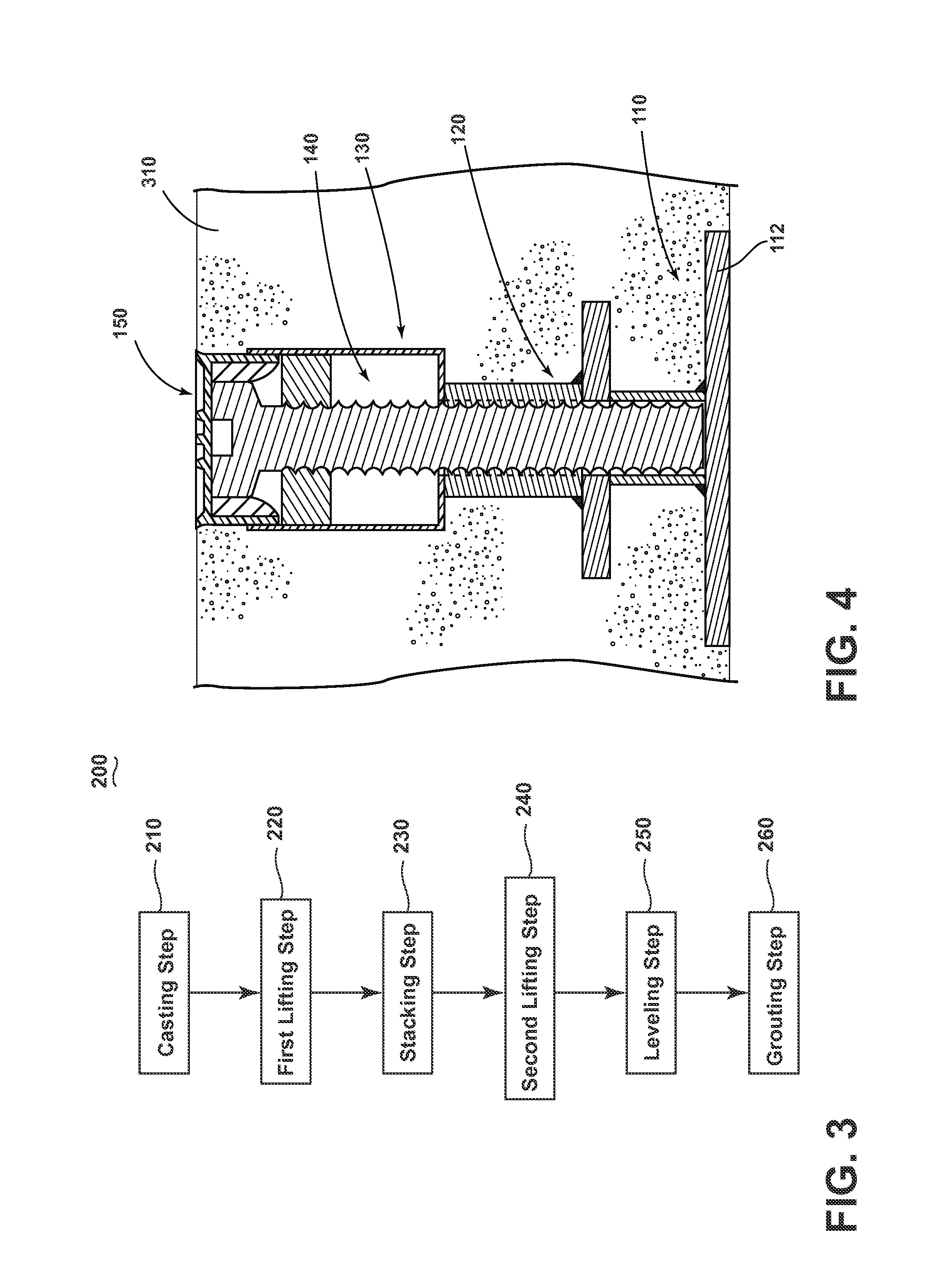
[0045]Turning now to the drawings and in particular to FIGS. 1 and 2, there is shown an exploded view and a sectional view of a lifting and leveling assembly 100 respectively according to an embodiment of the invention. The leveling and lifting assembly 100 comprises a rectangular leveling plate 110, an anchoring assembly 120, a thread protecting sleeve 130, an axially supported lifting bolt 140 and an end cap 150.

[0046]The rectangular lifting plate 110 comprises hollow cylinder 114 welded to a base plate 112. The base plate 112 and hollow cylinder 114 may be made from high strength steel and dimensioned to compliment the slab thickness.

[0047]The anchoring assembly 120 comprises a threaded sleeve in the form of a threaded hex nut 124 affixed to a rectangular anchor plate 122 having a circular through hole 128 coaxially aligned with the threaded hex nut 124 having a threaded through hole 126. The anchoring assembly 120 provides a bearing surface to axially support the axially support...


PUM


Abstract

A lifting and leveling assembly configured to be embedded in a precast concrete slab for lifting a leveling a precast concrete slab includes a base plate, a threaded sleeve, an anchor plate, a thread protecting sleeve, a threaded lifting bolt and an end cap. Rotating the threaded lifting bolt in a first direction positions a bolt head on the threaded lifting bolt above a top surface of a precast concrete slab to accommodate the attachment of a lifting device. Rotating the threaded lifting bolt in a second direction positions the bolt head beneath the top surface of the concrete slab and causes the threaded shaft to exert a force on the base plate to level the precast concrete slab.

Description

CROSS-REFERENCE TO RELATED APPLICATIONS[0001]This application claims the benefit of U.S. Provisional Patent Application No. 61 / 950,344, filed Mar. 10, 2014 which is incorporated herein by reference in its entirety.BACKGROUND OF THE INVENTION[0002]1. Field of the Invention[0003]The invention relates generally to the lifting and leveling of precast concrete slabs for use in the construction or repair of concrete surfaces.[0004]2. Description of the Related Art[0005]Precast concrete slabs are commonly used in the construction and repair of concrete surfaces such as concrete roads. Precast concrete slabs are lifted and placed in excavations and then leveled to be even with adjacent slabs. Grout is then pumped underneath the slab to fill and solidify any voids. It is common for precast concrete slabs to have lifting anchors embedded in the concrete so that the slabs may be lifted by a crane and rigging system. The slabs are leveled using precise surveys and excavation, plastic leveling s...

Claims


Application Information

Patent Timeline
Patent Type & Authority Patents(United States)
IPC IPC(8): E02D35/00E04G21/14E04B5/04B66F3/08E04B1/35
CPCE04G21/142E04B5/04E04B1/3511B66F3/08E04B2103/02E04B2001/3588B66C1/666E04G15/04E01C23/10
Inventor FRANCIES, III, SIDNEY E.
Owner FRANCIES III SIDNEY E
Why Eureka
Try Eureka