
Breathing assistance apparatus

a technology of breathing assistance and apparatus, which is applied in the direction of valve details, valve arrangements, life-saving devices, etc., can solve the problems of difficult to minimize the base flow rate, difficult to control the flow rate value in the duct b>110/b>, and disrupt the precision of the control of the respiratory gas flow, etc., to achieve efficient and reliable control of the gas volume, the effect of finely controlling the small target valu

Active Publication Date: 2011-06-09
RESMED PARIS
View PDF17 Cites 65 Cited by
  • Summary
  • Abstract
  • Description
  • Claims
  • Application Information

AI Technical Summary

Benefits of technology

[0085]Yet another purpose of the invention is to provide efficient and reliable means for controlling the operation of the apparatus in volumetric modes. In particular, it would be advantageous to finely control small target values of the volume of gas to be delivered to a patient.
[0086]Finally, another purpose of the invention is to allow the benefits of a configuration in which the inhalation valve is capable of operating proportionally to be maximized.
[0098]associated to a program allowing the selection to be made in real time from a pressure or flow rate signal.so that the association of a direct closed regulation loop for the selection of a reference value parameter with a valve permitting proportional operation, allows real time control of barometric and volumetric operating modes of the apparatus, between the inhalation and expiratory phases and during these phases.
[0117]In such process, when the apparatus operates, the micro-turbine can operate constantly and the valve can be controlled by the selective connection of a pneumatic control line of the said valve with the micro-turbine.

Problems solved by technology

In particular, when operating in volumetric mode, it is possible that very precise control of the flow rate value in the duct 110 is difficult.
In this case indeed, the variations in load of the turbine are likely in certain conditions to disrupt the precision of the control of the respiratory gas flow in the duct 110.
Secondly, it can be difficult to minimize the base flow rate.

Method used


Image

  • Breathing assistance apparatus
  • Breathing assistance apparatus
  • Breathing assistance apparatus

Examples


Embodiment Construction

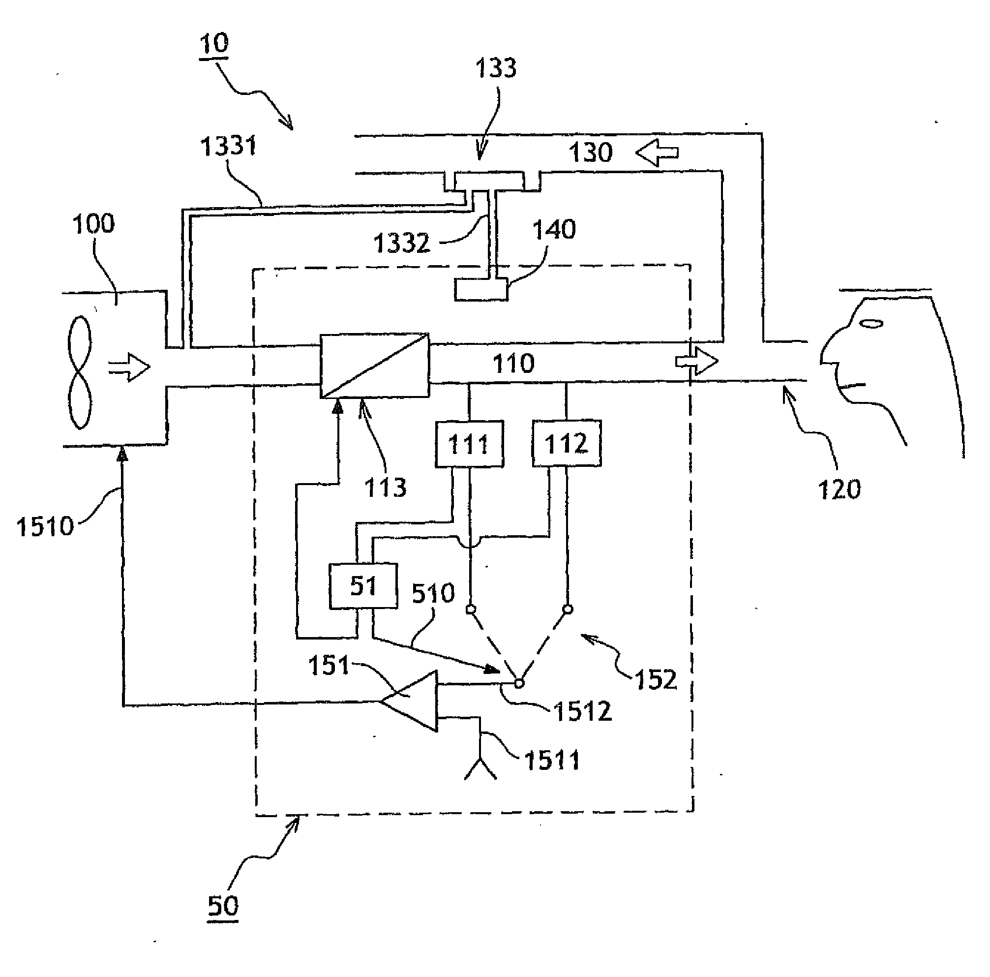
[0126]In reference to FIG. 2, a first embodiment of the invention has been represented.

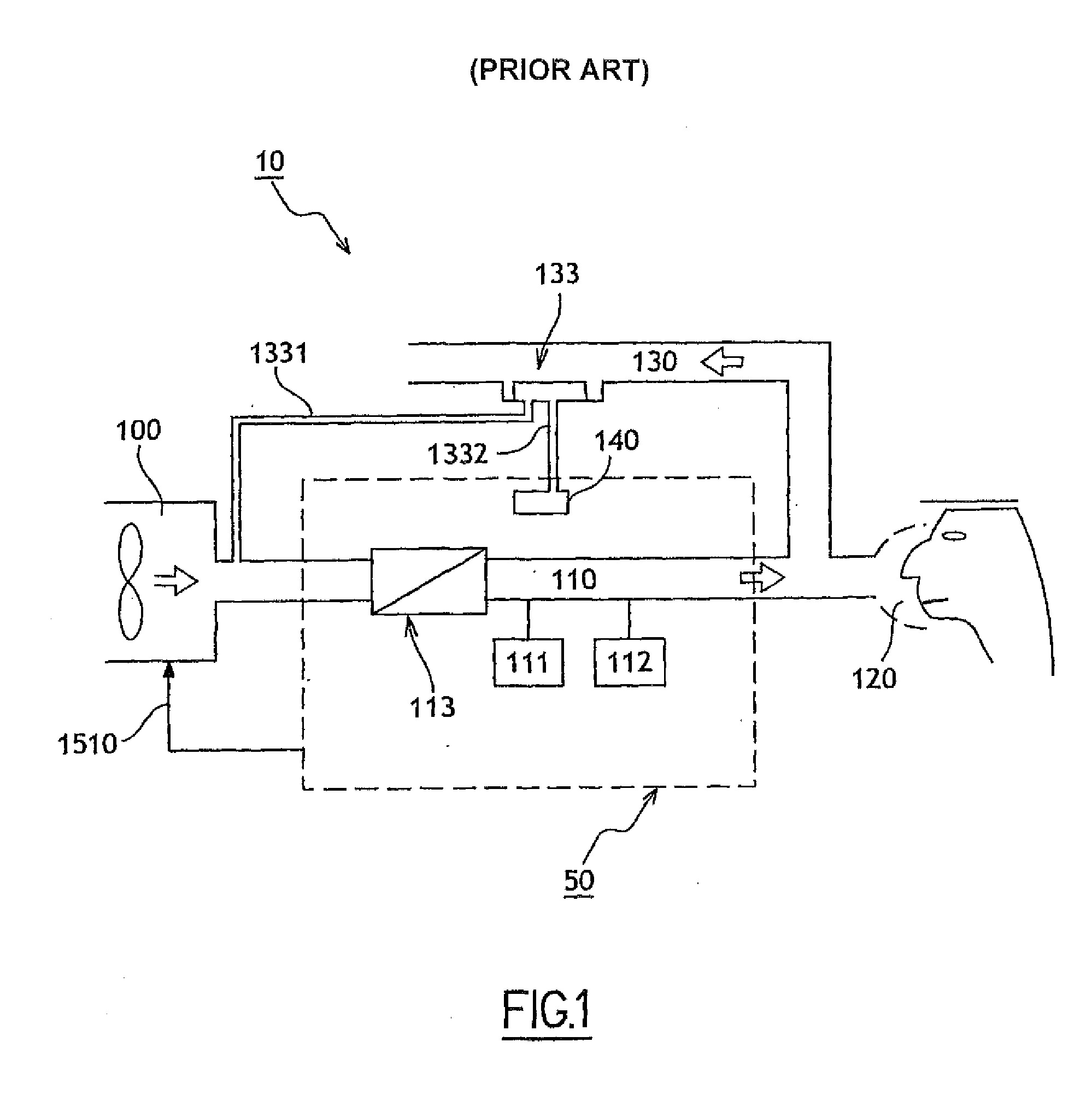
[0127]In this figure, as in FIG. 4, the apparatus represented comprises the elements that have already been described in reference to FIG. 1. These elements will be represented with the same references.

[0128]Consequently in this figure, we find all of the elements which make up the apparatus of FIG. 1.

[0129]In particular, we find the pressurized gas source 100.

[0130]Within the scope of the invention, this source is a centrifugal fan type turbine (which is to say that its output is on the side of the rotating element, for example via a tangential manifold pipe) with an axial air intake (which is to say that its air input is more or less aligned with the spindle of the rotating part of the turbine).

[0131]Also, this gas source has a particularly low inertia, of around 150 gcm2.

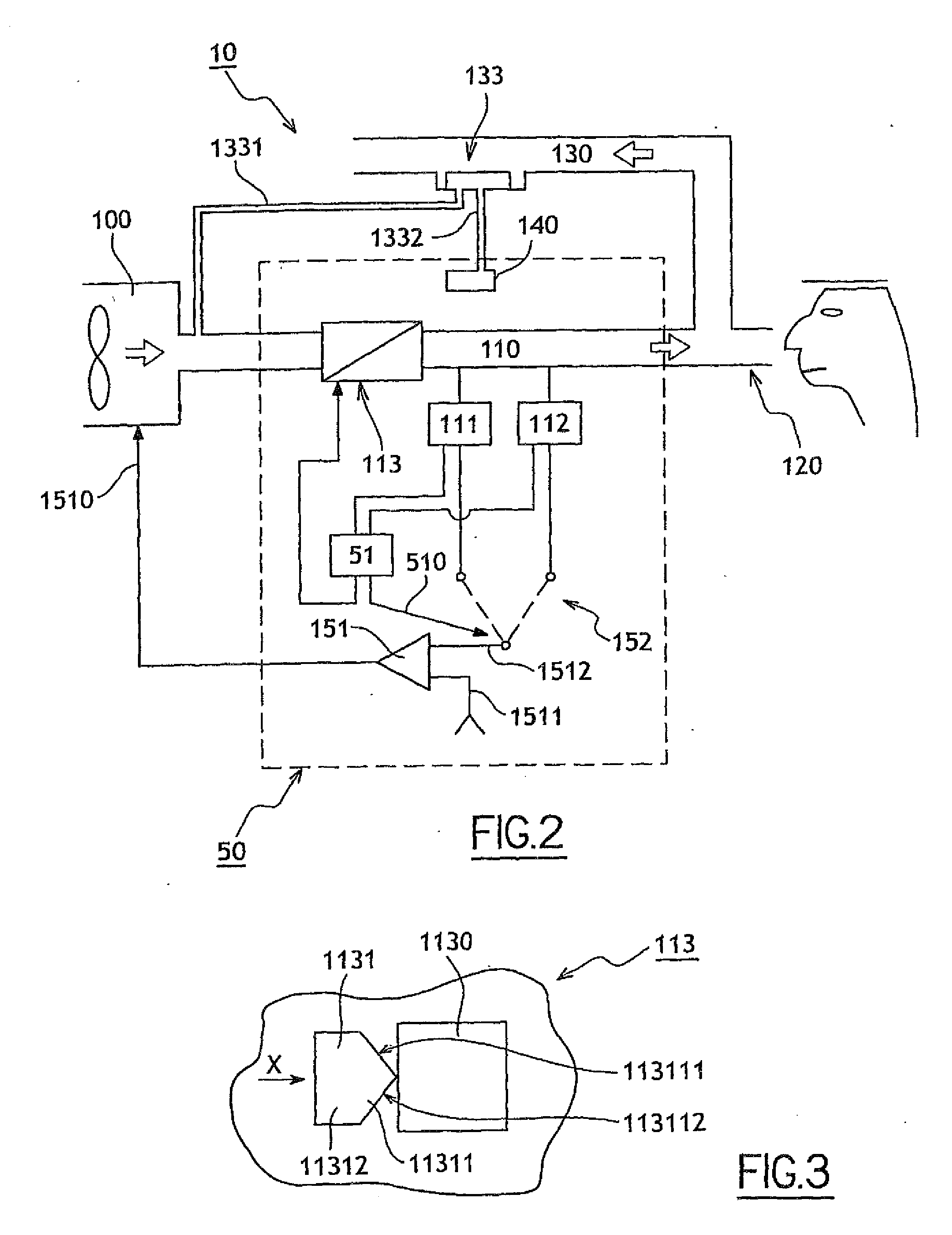
[0132]We also find an inhalation valve 113 that is capable of operating proportionally.

[0133]More precisely, this valve prefe...


PUM


Abstract

A breathing assistance apparatus operates in alternating inhalation and expiratory phases wherein a) the control means of the apparatus comprise selection means capable of selecting a pressure parameter or a flow rate parameter to define; b) the reference value for the gas source, the selection means are controlled by an automatic control unit being: I) connected to pressure and flow rate sensors situated on the inhalation duct to form a direct closed regulation loop for selecting a reference value parameter, II) associated to a program allowing the selection to be made in real time from a pressure or flow rate signal, so that the association of a direct closed regulation circuit for the selection of a reference value parameter with a valve permitting proportional operation, allows real time control of barometric and volumetric operating modes, between and during the inhalation and expiratory phases. The invention also concerns associated operating processes.

Description

CROSS-REFERENCE TO RELATED APPLICATIONS[0001]This application is a continuation of U.S. application Ser. No. 10 / 550,247, filed on Aug. 15, 2006, which is a national phase entry under 35 U.S.C. §371 of International Application No. PCT / 1B2004 / 001298, filed on Mar. 24, 2004, which claims the benefit of French Application No. 0303538, filed on Mar. 24, 2003, and of U.S. Provisional Patent Application No. 60 / 495,923, filed on Aug. 18, 2003, the disclosure of which is hereby incorporated herein by reference.BACKGROUND OF THE TECHNOLOGY[0002]This invention concerns a breathing assistance apparatus capable of operating in alternating inhalation and expiratory phases and comprising:[0003]a pressurized respiratory gas source,[0004]control means capable of transmitting a reference value of a gas related parameter to the said gas source,[0005]an inhalation duct to supply the gas from the gas source to a patient,[0006]an expiratory duct for the expiratory gas of the patient,[0007]a valve on the...

Claims


Application Information

Patent Timeline
IPC IPC(8): A61M16/20A61M16/00A62B9/00
CPCA61M16/00A61M16/0066A61M16/20A61M2016/0021A61M16/206A61M2016/0042A62B9/006A61M16/0057A61M16/06A61M2016/0039A61M16/0069A61M16/203A61M16/024
Inventor CHALVIGNAC, PHILIPPE
Owner RESMED PARIS
Features
  • Generate Ideas
  • Intellectual Property
  • Life Sciences
  • Materials
  • Tech Scout
  • Unparalleled Data Quality
  • Higher Quality Content
  • 60% Fewer Hallucinations
Learn More