Ventilation System With System Status Display
- Summary
- Abstract
- Description
- Claims
- Application Information
AI Technical Summary
Benefits of technology
Problems solved by technology
Method used
Image

Examples
examples
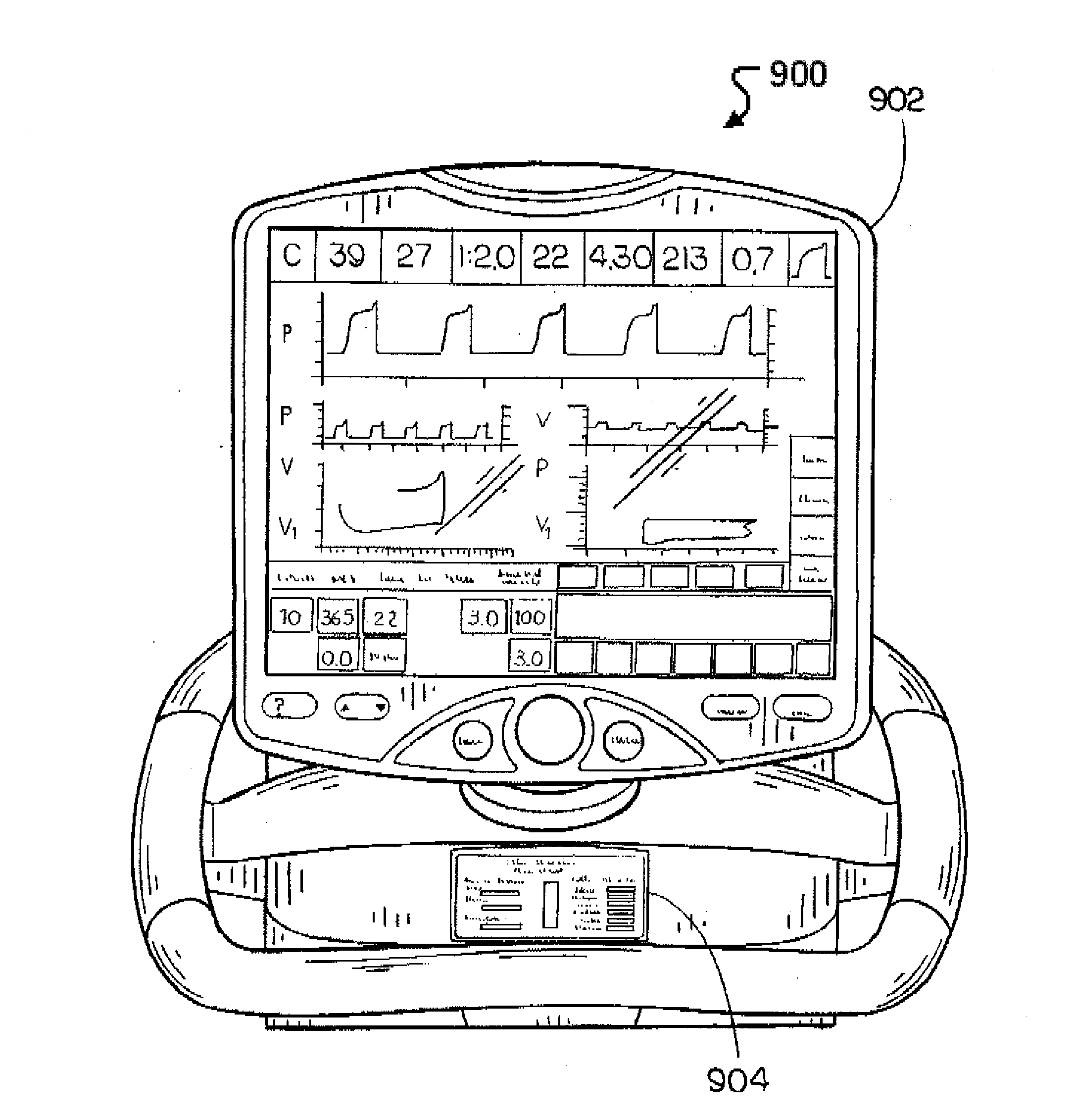
[0118]The following are embodiments of displays that could be shown on the SSD of a medical ventilator.
[0119]The following are embodiments of pressure traces or manometer that could be displayed on SSD to allow an operator to determine from the SSD the ventilator's ability to support breath delivery to the patient.
[0120]In one embodiment, as the SSD displays a pressure trace or manometer that indicates that pressure is transitioning between two points, such as PEEP and Peak Inspiratory Pressure (PPEAK). As illustrated in FIG. 3, an embodiment of a screen shot of an SSD, the SSD displays a pressure trace that provides an indication of the rise time of the pressure and the pressure levels. Further, as shown in the FIG. 3 embodiment, the SSD provides a continuous display of the minimum and peak inspiratory pressure levels. In one embodiment, the pressure trace can be scaled to provide for the highest level of resolution on the SSD.
[0121]While not shown in this embodiment, in an alterna...
PUM
 Abstract
Description
Claims
Application Information
 - Generate Ideas
- Intellectual Property
- Life Sciences
- Materials
- Tech Scout
- Unparalleled Data Quality
- Higher Quality Content
- 60% Fewer Hallucinations
Browse by: Latest US Patents, China's latest patents, Technical Efficacy Thesaurus, Application Domain, Technology Topic, Popular Technical Reports.
© 2025 PatSnap. All rights reserved.Legal|Privacy policy|Modern Slavery Act Transparency Statement|Sitemap|About US| Contact US: help@patsnap.com