Method and apparatus for purging air from automatic lubrication systems

a technology of automatic lubrication and air purging, which is applied in the direction of engine lubrication, gas/liquid distribution and storage, water mains, etc., can solve the problems of air leakage in the suction of the filling system, equipment that is often not compatible with mining, earth moving and construction equipment,

Active Publication Date: 2011-06-09
IFIELD ENG
View PDF12 Cites 12 Cited by
  • Summary
  • Abstract
  • Description
  • Claims
  • Application Information

AI Technical Summary

Benefits of technology

[0016]In a first aspect the present invention provides an apparatus for purging gas from an automatic lubrication system of the type incorporating a pump arranged to pump lubricant from a reservoir through delivery lines to one or more injectors, said apparatus including one or more gas purge valves associated with at least some of the injectors, arranged to open and dump shots of lubricant containing unacceptable levels of gas before they reach the associated injector, each gas purge valve incorporating one or more components communicating with and reactive to conditions in the pump and arranged to open the gas purge valve when abnormal pump operation is sensed due to the presence of gas in the lubricant.

Problems solved by technology

Known automatic centralised lubrication systems provide a useful function, but have some problems.
It is not necessarily obvious to the machine operator when the automatic lubrication system is not delivering grease to all the bearings, due to some malfunction of the lubrication system.
More sophisticated systems have alarms and sensors to provide oversight of operation, often in combination with an electronic sentry system, but such equipment is often not compatible with mining, earth moving and construction equipment as being too unreliable in the harsh environment in which these machines operate.
Malfunction of the lubrication system can be caused by air entrained in the grease in a reservoir.
There may be an air leak in the suction of the filling system:
Some pump systems use a reservoir without a follower piston and a motor driven paddle to assist in mobilising the grease to the pump inlet that will also assist in air release with some greases, but this does not always effectively bleed the air.
The delivery line effectively becomes a hydraulic accumulator as the air in the line becomes compressed and presents a potential safety hazard.
Grease that is delivered to the bearings may be aerated, reducing the lubrication effectiveness.
Altogether this is a long and costly process having significant impact on machine productivity.

Method used


Image

  • Method and apparatus for purging air from automatic lubrication systems
  • Method and apparatus for purging air from automatic lubrication systems
  • Method and apparatus for purging air from automatic lubrication systems

Examples


Embodiment Construction

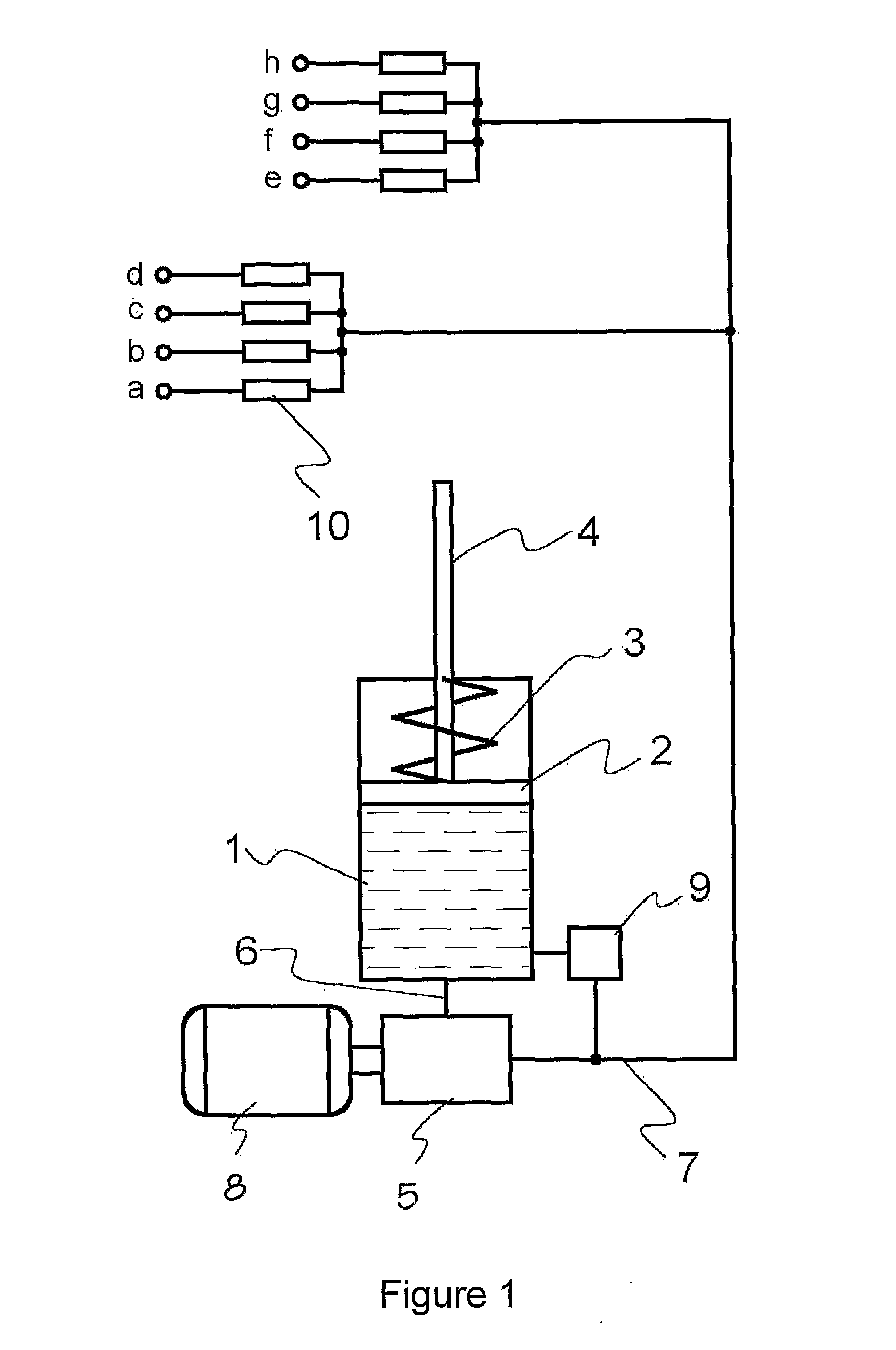
[0042]The basic operation of different forms of automatic lubrication systems will now be described with reference to FIGS. 1 to 4.

[0043]FIG. 1 shows a very basic motor driven centralised lubrication system. Grease is loaded into a reservoir 1. The means for loading the grease are not shown, but would typically be by way of a drum pump driven manually, electrically or by compressed air. As the grease is loaded, follower piston 2 is pushed upwards against a spring 3. A rod 4 extends out of the top of the reservoir 1 and provides a visual indicator of the amount of grease in the reservoir.

[0044]A grease pump 5 has an inlet connection 6 and a delivery line 7. The pump can be of a simple piston type, either rotary or reciprocating, and is most commonly an automatically reciprocating piston pump powered by compressed air. Power is provided by motor 8, which may be electric, pneumatic, hydraulic or even manually powered. A vent valve 9 opens when the pump is off to relieve any pressure th...


PUM


Abstract

An automatic lubrication system where grease is dispensed to injectors from a pump having a grease piston (42) reciprocated by a connecting rod from an oil piston (43) driven by alternating hydraulic pressure, is provided with air purge valves (41) associated with each injector. The air purge valves detect abnormal operation of the piston movement due to air in the grease by way of indicators (45) and (46) communicating with chambers in the pump, and open the air purge valve to dump air laden grease into a recovery reservoir (48). A sensor in the air purge valve warns the operator of purge valve operation, alerting the operator to a possible system malfunction.

Description

FIELD OF THE INVENTION[0001]This invention relates to a method and apparatus for purging air from automatic lubrication systems by providing a valve to purge air or gas from lubricant before it is delivered to machinery bearings, and has been devised particularly though not solely for use in heavy machinery of the type used in mining or earth moving.BACKGROUND OF THE INVENTION[0002]Automatic lubrication systems are used on many types of machinery, from large fixed plant to smaller mobile construction and mining equipment. In general they replace procedures requiring manual application using grease guns and the like.[0003]Throughout this specification the lubricant is referred to as grease, being the most common lubrication substance, but the term is to be understood to include other lubricants such as oil and synthetic liquids or gels.[0004]Known automatic centralised lubrication systems provide a useful function, but have some problems. It is not necessarily obvious to the machine ...

Claims


Application Information

Patent Timeline
Patent Type & Authority Applications(United States)
IPC IPC(8): F16N7/38F16N29/02F16N29/04F16N13/00F01M11/00F16K37/00F16K31/00
CPCF16N39/002F16N11/10Y10T137/7761Y10T137/8242
Inventor IFIELD, BENJAMIN
Owner IFIELD ENG
Why Eureka
Try Eureka