

Superconducting magnetizer
a superconducting magnetizer and superconducting technology, applied in the field of superconducting magnetizers, can solve the problems of overpowering power supply requirements, overthermal management requirements, and complex cooling schemes
- Summary
- Abstract
- Description
- Claims
- Application Information
AI Technical Summary
Problems solved by technology
Method used
Image

Examples
Embodiment Construction
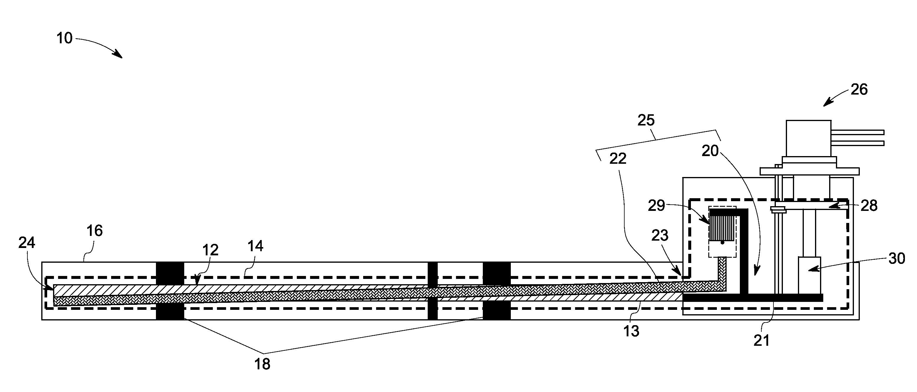
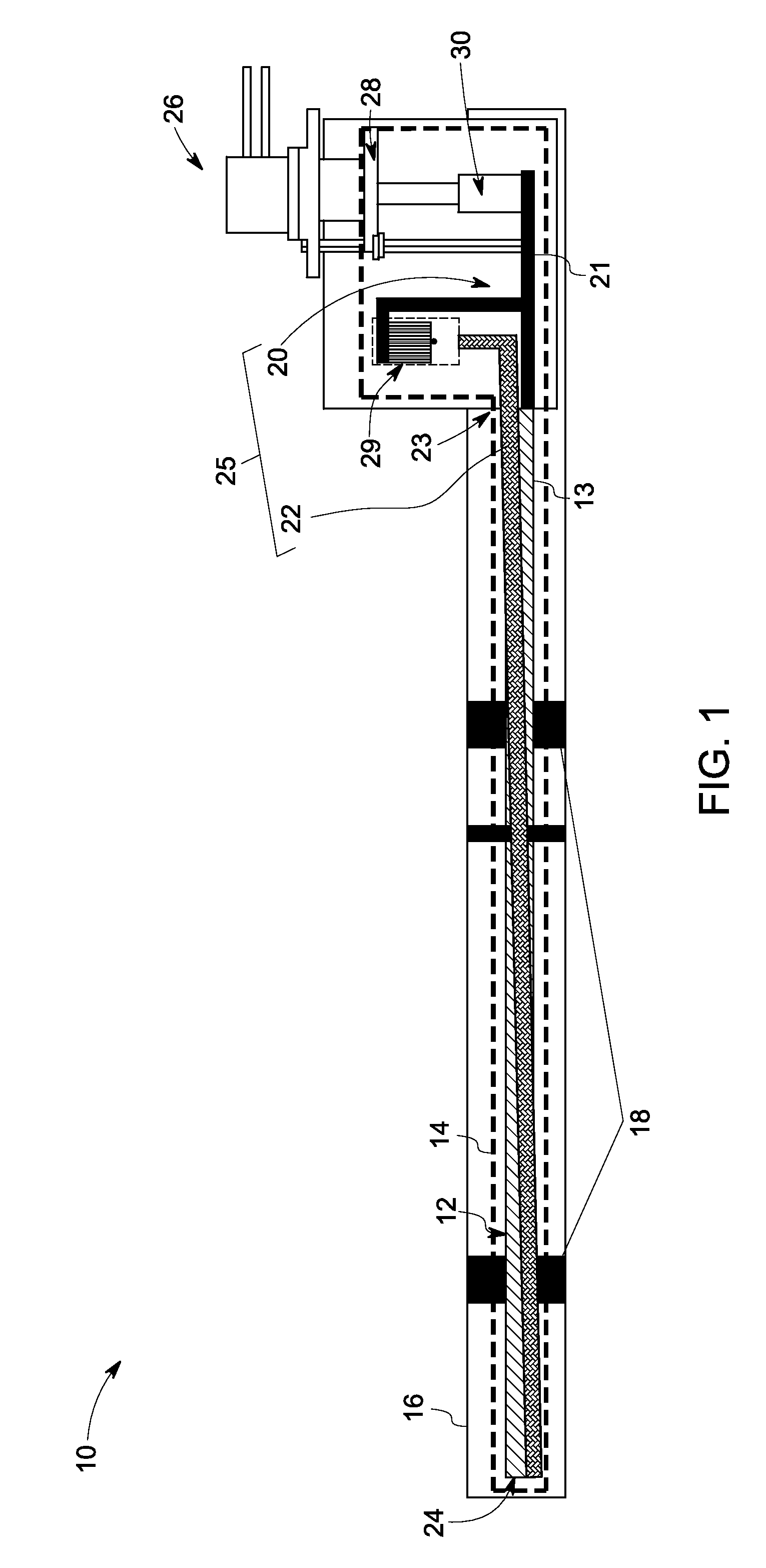
[0019]In accordance with the embodiments discussed herein, a superconducting magnetizer is disclosed. The superconducting magnetizer includes a thermal shield disposed within a vacuum chamber. A superconducting magnet is disposed within the thermal shield and configured to generate a magnetic field in response to an electric current supplied to the superconducting magnet. A heat transfer device including at least one of a thermal conduction device, and a heat pipe is disposed contacting the superconducting magnet. A cryo-cooler is coupled to the heat transfer device and configured to cool the superconducting magnet via the heat transfer device. The superconducting magnet, the thermal shield, or combinations thereof are supported against the vacuum chamber via a support device. The exemplary superconducting magnetizer has minimum power supply requirements, and minimum thermal management requirements during cool-down cycles.
[0020]Referring to FIG. 1, a superconducting magnetizer 10 in...
PUM
| Property | Measurement | Unit |
|---|---|---|
| magnetic forces | aaaaa | aaaaa |
| magnetic field | aaaaa | aaaaa |
| superconducting | aaaaa | aaaaa |
Abstract
Description
Claims
Application Information