

Superconducting switch, superconducting magnet and MRI
a superconducting magnet and switch technology, applied in the direction of superconducting magnets/coils, instruments, magnetic bodies, etc., can solve the problems of high thermal efficiency of the insulating substrate existing between the stability of the superconducting switch is low, and the superconductor approaches the critical temperature and quenching is easy to occur. , to achieve the effect of increasing the thermal efficiency of the superconducting film and the heater,
- Summary
- Abstract
- Description
- Claims
- Application Information
AI Technical Summary
Benefits of technology
Problems solved by technology
Method used
Image

Examples
embodiment 1
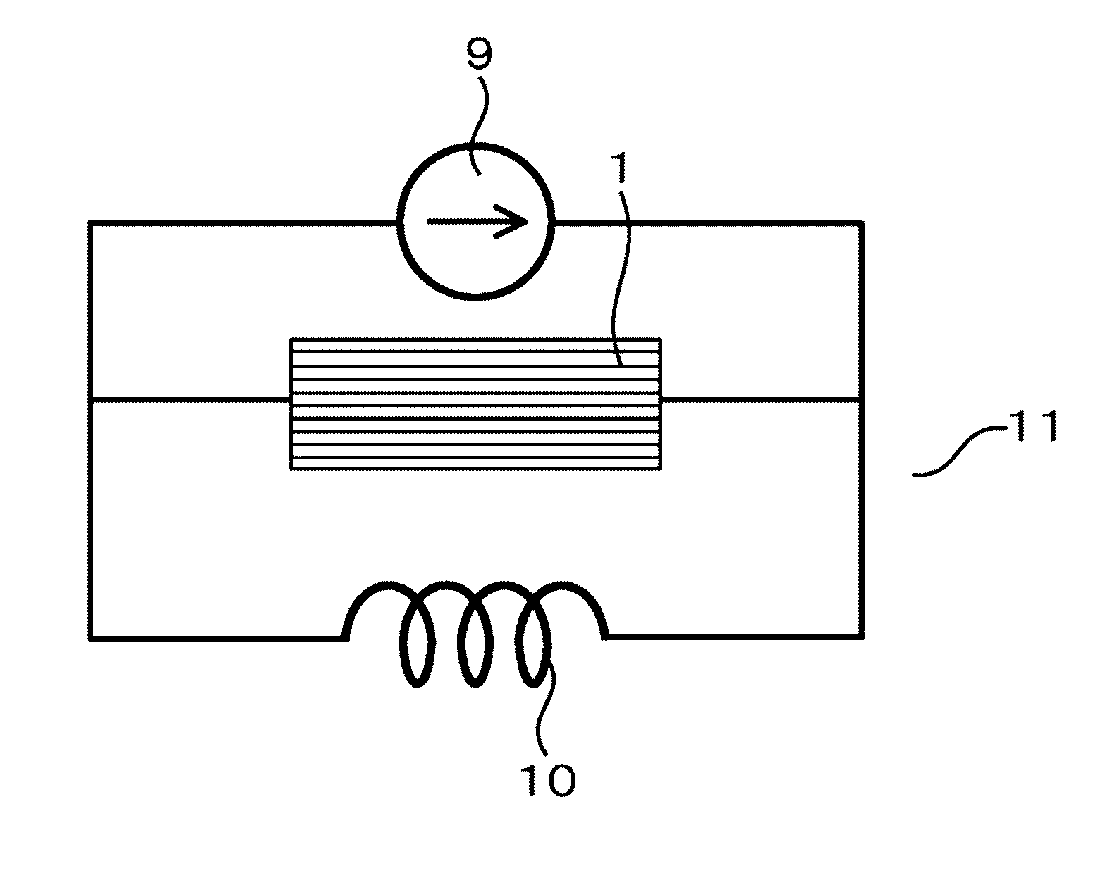
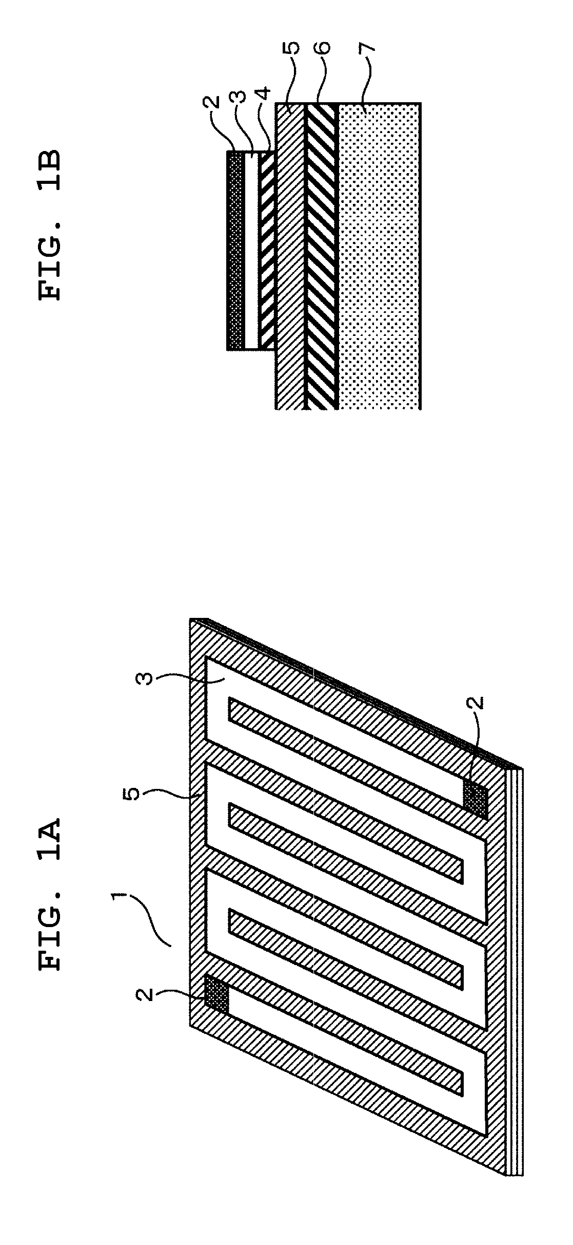
[0023]FIG. 1A is a perspective view of a superconducting switch 1 common to respective embodiments, and FIG. 1B is a partial sectional view thereof. Since components except a substrate 7 are film-like, the thickness of the substrate 7 is made a sufficient thickness to keep the rigidity of the superconducting switch 1. A heater 6 is a heating body for switching between the ON state and the OFF state of the superconducting switch 1, and is connected to a not-shown heater power supply. The heater 6 can be formed of a metal foil or a metal foil cut into a circuit pattern shape, and can also be formed by evaporating a circuit pattern on the substrate 7. An insulating film 5 is a film to secure electrical insulation between the heater 6 and a conductive film 4. The conductive film 4 can be formed by evaporating a conductive material on the insulating film 5. The conductive film 4 is preferably formed of an evaporated metal film or a conductive ceramic. The conductive film 4 is electricall...
embodiment 2
[0031]In an embodiment described below, only different points from the embodiment 1 will be described. FIGS. 4A and 4B are partial sectional views of a superconducting switch 1 in which a protecting film 12 is laminated. The protecting film 12 is provided on a surface (cooling surface) of a MgB2 film at an opposite side to a substrate. In FIG. 4A, the protecting film 12 is provided only on a MgB2 film 3, and in FIG. 4B, the protecting film 12 is provided to cover not only the MgB2 film 3 but also a conductive film 4 and an insulating film 5.
[0032]In this embodiment, the MgB2 film 3 in the OFF state does not directly exchange heat to liquid helium or helium gas, but exchanges heat through the protecting film 12. When the protecting film 12 exists, as compared with a case where the MgB2 film 3 is directly exposed to helium and is cooled, the MgB2 film 3 is hard to cool. The protecting film 12 preferably has a thermal conductivity of 10 W / m / K or more.
[0033]The MgB2 film 3 generates hea...
embodiment 3
[0034]FIG. 5 shows an arrangement example of a heater electrode couple 8. In this embodiment, a conductive film 4 functions also as a heater. When a superconducting switch 1 is placed in the OFF state, and a superconducting coil 10 is excited, the electrical potential difference RIR is applied between both ends of an electrode 2, both ends of a MgB2 film 3, and both ends of the conductive film 4. For example, when the electrical potential of one end is zero (volt), the other end has the electrical potential of RIR (volt). As shown in FIG. 5, consideration is given to a case where the heater electrode couple 8 are placed at two points of the conductive film 4 equally spaced from one end of the electrode 2. When the length of a current path, which is made of the MgB2 film 3 and the conductive film 4, between both the electrodes 2 is 1, the distance from one end (electrode 2) of the current path to each of the heater electrode couple 8 is x, and the electrical potential at one end of t...
PUM
 Abstract
Description
Claims
Application Information