Medical Devices, Methods of Producing Medical Devices, and Projection Photolithography Apparatus for Producing Medical Devices

a technology of medical devices and projection photolithography, which is applied in the direction of blood vessels, printers, instruments, etc., can solve the problems of high technology cost, significant morbidity and mortality, and low rate of re-intervention procedures, so as to reduce the thickness of the stent strut in each layer, reduce the diameter of the stent strut, and reduce the thickness of the stru

Inactive Publication Date: 2011-11-10
WALKER JEFFREY P +1
View PDF4 Cites 57 Cited by
  • Summary
  • Abstract
  • Description
  • Claims
  • Application Information

AI Technical Summary

Benefits of technology

[0023]The present invention also presents a design and method for reducing stent strut diameter (thickness), in addition to reducing strut dimensions, by incorporating two or more nested stents (e.g., stent segments and/or layers) in a concentric superstructure to form a scaffolded stent. The stent layers may be joined by one or more connection points that are formed using a bonding process, such as diffusion bonding, welding, etc., and the stent segments in a given layer may be joined by one or more strut-like connectors (see, e.g., FIG. 6). Unlike most other commercial designs that utilize a single scaffold comprised of many design elements, the present invention describes multiple, ultra-thin stent layers that are assembled into a larger superstructure that is implanted as a whole unit. The multilayer, nested structure reduces strut thickness in each layer without necessarily sacrificing radial strength of the stent by increasing numbers of layers in the stent. As a result, the radial stiffness of each layer of the stent decreases, thereby decreasing the bending stiffness significantly (i.e., the stent is very flexible), but the cumulative stiffness of the stent is equivalent to stiffness of conventional single-layer or solid stents. In addition, the radial force on the stent can be distributed through many contact points (thereby reducing contact stress).
[0024]Using projection lithography to project light onto the inner and outer stent surfaces enables the formation of a stent from a single tube or cylinder with a customized radius, curvature, contours, surface properties, length, and width on each individual stent strut on both the inner diameter (ID) and outer diameter (OD) of the stent. The ability to apply predetermined patterns to the internal surfaces of the struts is a major advantage over conventional techniques. Alternatively, the present projection lithography apparatus and method can be used on a flat sheet, foil or film of a medically- and/or biologically-acceptable material (e.g., a biologically-acceptable metal or alloy), which can be rolled (or curved) and welded after etching. The present methods allow the patterning of intricate 3D shapes on both the external and internal strut surfaces that can be achieved by a series of exposures and etchings (e.g., to a controlled depth). The utility of such patterning may include, but is not limited to, promotion or inhibition of cellular migration, cellular adhesion, cell shape, cell-based sensing, patterns of tissue growth, cellular differentiation, cellular apoptosis, and cellular chemistry. Stents typically have a mesh design, with a great deal of open area within the structure. Applying patterns to the internal surface of the struts is possible, even where the metal fill factor (i.e., Σarea of the struts/τarea of the openings) is relatively low. Metal coverage area of stents generally ranges from 8% to 24%, but a majority of stents are between 11-18% when fully expanded, resulting in the ability to pass light around stent struts opposite the face of the inner surface to be patterned. FIG. 2 illustrates the small amount of shadowing that occurs as a result of a stent strut 21 placed in line with a projection lithography system designed to etch contours on the inner surface 22 of a given strut.
[0025]Another advantage of the system is that the photomask is located some distance away from the target, resulting in an extended mask life since there is little to touch or damage the mask. The mask (see, e.g., mask 4 in FIG. 1) is hidden inside of the system at some distance from the stent surface and can be manufactured at a larger scale (4:1 scale, for example). This allows for a less expensive mask manufacturing process. Additionally, the mask is may be scaled significantly larger than the dimensions of the pattern to be produced, making the mask easier to manufacture as well as minimizing the effects of mask errors, contamination by particulates and mask motion errors. This design allows for an extremely high resolution can be achieved which can be calculated by the formula CD=ki·

Problems solved by technology

Although the rates of re-intervention procedures are generally low, complications such as thrombosis, delayed healing, and/or non-incorporation of stent struts into the vascular wall continue to result in significant morbidity and mortality, requiring local drug delivery and/or prolonged systemic anti-platelet therapy to achieve acceptable therapeutic outcomes.
These technologies are highly expensive and have measurable adverse side effects that contribute to patient morbidity and mortality.
There are significant adverse effects of blood flow disturbance caused by the shape and/or configuration of the implanted stent that, in turn, causes disruption of normal endothelial cell function.
Analysis of blood flow patterns in and around embedded stent struts has demonstrated that there are significant areas of flow disruption that can lead to reduced shear stress on endothelial cells.
Failure of the stent to fully expand and fill a curved structure can lead to adverse events in the stented structure that could include thrombosis, migration, and/or inflammation.
However, there are still problems that need to be addressed.
However, despite these improvements, delayed healing and acute thrombosis continue to present major problems for patients and clinicians and require inflexible and aggressive anti-platelet drug therapies for weeks to months following stent implantation.
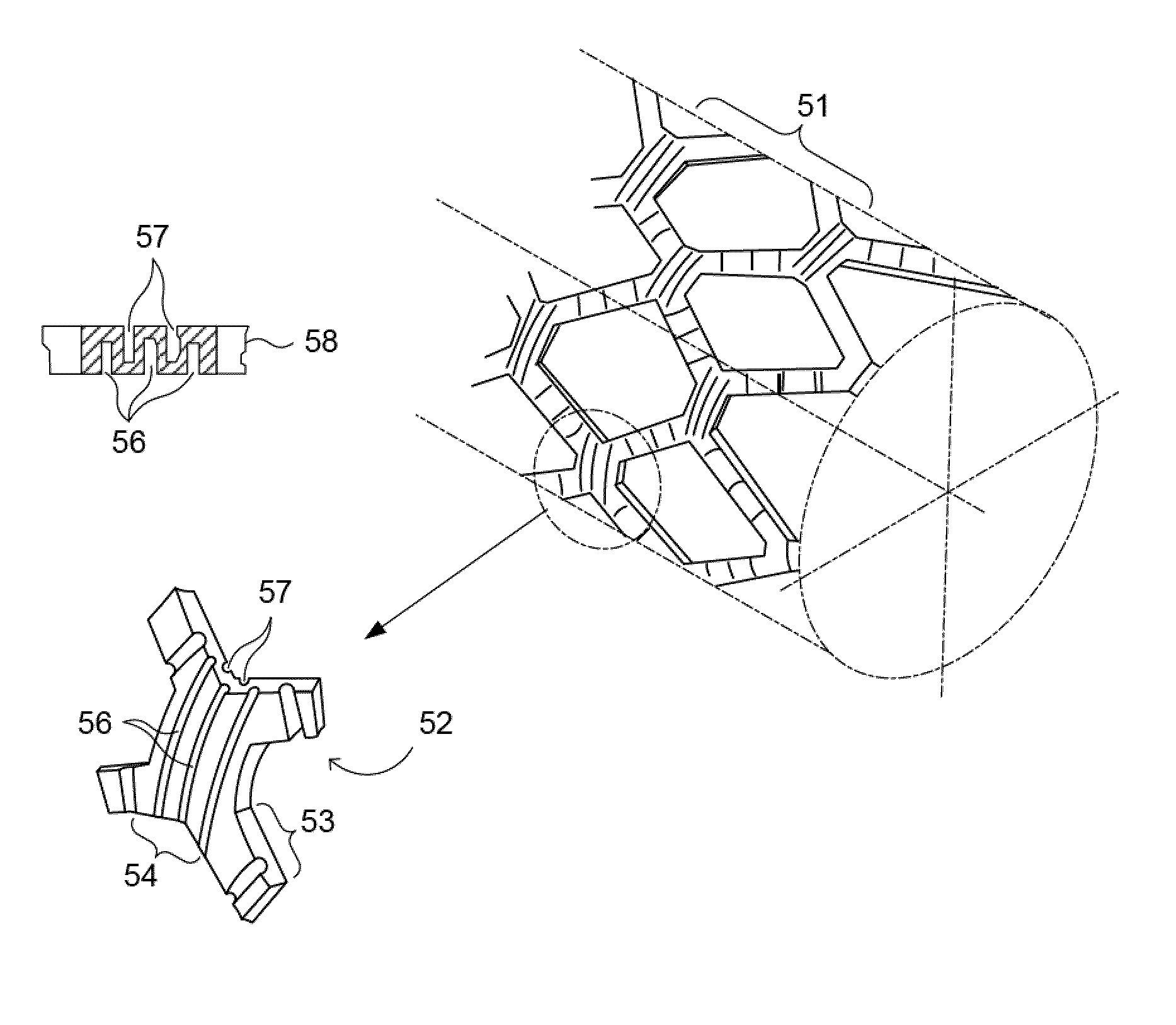
Current commercial manufacturing methods for stents are not able to solve the difficulty of constructing hemodynamically designed stent struts with contoured surfaces, particularly on the internal diameter (ID) of the stent strut.
However, these processes are incapable of controlling the geometric contour of stent struts on both inner and outer diameters with micron-scale precision in the absence of photolithographic methodologies.
However, in the disclosure of Berglund, there is little discussion about how these struts might be manufactured.
However, lasers do not cut edges; rather they melt material and controlling with micron-scale precision a melting process would be highly difficult and impractical.
The post-process techniques described in the '737 patent to smooth away contour from a relatively complex polygonal shape may require significant and time-consuming modification and be relatively impractical both in terms of controllability and time required to achieve efficient product output.
The resolution of such systems is around 3-5 μm under optimum circumstances, and the systems are very sensitive to particulate contamination and mechanical damage.
However, the apparatus of Hines is only suitable for application of a pattern to the outer diameter (OD, or outer surface) of the tubular substrate and uses contact photolithography to transfer the process from the photomask to the cylindric

Method used


Image

  • Medical Devices, Methods of Producing Medical Devices, and Projection Photolithography Apparatus for Producing Medical Devices
  • Medical Devices, Methods of Producing Medical Devices, and Projection Photolithography Apparatus for Producing Medical Devices
  • Medical Devices, Methods of Producing Medical Devices, and Projection Photolithography Apparatus for Producing Medical Devices

Examples


Embodiment Construction

[0052]Reference will now be made in detail to various embodiments of the invention, examples of which are illustrated in the accompanying drawings. While the invention will be described in conjunction with certain embodiments, it will be understood that they are not intended to limit the invention to these embodiments. On the contrary, the invention is intended to cover alternatives, modifications and equivalents that may be included within the spirit and scope of the invention as defined by the appended claims. Furthermore, in the following disclosure, numerous specific details are given to provide a thorough understanding of the invention. However, it will be apparent to one skilled in the art that the present invention may be practiced without these specific details. In other instances, well-known methods, procedures, components, and circuits have not been described in detail, to avoid unnecessarily obscuring aspects of the present invention.

[0053]The present invention concerns a...


PUM


Abstract

Stents and other medical devices that can have specific geometric configurations (curves, contours, tapers) and/or patterns (e.g., grooves) thereon, methods of making such medical devices, and apparatuses for making such medical devices are disclosed. Projection photolithography is used to define patterns the medical devices. The methods can form grooves, ridges, channels, holes, wells, and other geometric patterns (e.g. parallelograms such as squares, rectangles and other trapezoids; triangles, pentagons, spirals, hexagons, etc.) on the surface of both the inner and outer diameters (e.g., on both the inner and outer surfaces) of stents or other cylindrical, tubular or curved-surface medical devices, allowing the manufacture of stents having customized geometry/contours on all surfaces, which can minimize endothelial surface disruption of blood flow.

Description

RELATED APPLICATIONS[0001]This application claims the benefit of U.S. Provisional Patent Appl. Nos. 61 / 331,803, filed May 5, 2010 (Attorney Docket No. JPW-001-PR); 61 / 348,110, filed May 25, 2010 (Attorney Docket No. SON-002-PR); and 61 / 348,210, filed May 25, 2010 (Attorney Docket No. SON-003-PR), each of which is incorporated herein by reference in its entirety.FIELD OF THE INVENTION[0002]The present invention relates to stents and other medical devices that can have specific patterns and geometric configurations (curves, contours, tapers) on the inner and / or outer surfaces thereof, methods of manufacturing such stents and medical devices, and an apparatus capable of forming such stents and medical devices with a high level of precision.DISCUSSION OF THE BACKGROUND[0003]In vascular medicine, the use of stents in blood vessels has been highly successful in reducing both short-term and long-term complications of balloon angioplasty (e.g., elastic recoil, restenosis) and several genera...

Claims


Application Information

Patent Timeline
IPC IPC(8): A61F2/82G03B27/52G03F7/20A61F2/06
CPCA61F2/915A61F2002/068A61F2230/0008A61F2230/0015A61F2230/0054A61F2250/0029G03B27/52G03F7/24A61F2210/0076A61F2240/001
Inventor WALKER, JEFFREY P.DRUBETSKY, LEV
Owner WALKER JEFFREY P
Why Eureka
Try Eureka