Docking Station And Device Adapter For Use In A Docking Station

a docking station and device technology, applied in the direction of coupling device connections, electrical apparatus casings/cabinets/drawers, instruments, etc., can solve the problems of chaotic desktop arrangement and inconvenience for users

Active Publication Date: 2011-06-09
UNKNOWN
View PDF55 Cites 91 Cited by
  • Summary
  • Abstract
  • Description
  • Claims
  • Application Information

AI Technical Summary

Problems solved by technology

When charging such a portable electronic device, a user often has to remove the cover case before placing the portable electronic device inside the docking station for charging the battery.
Such additional steps of removing and refitting the cover case cause inconvenience to the user each time when the portable electronic device is to be placed in the docking station for the battery charging and / or data transfer operation of the portable electronic device.
When different types or models of portable electronic devices are in use, multiple different docking stations are to be provided, which can create a chaotic desktop arrangement.

Method used


Image

  • Docking Station And Device Adapter For Use In A Docking Station
  • Docking Station And Device Adapter For Use In A Docking Station
  • Docking Station And Device Adapter For Use In A Docking Station

Examples


first embodiment

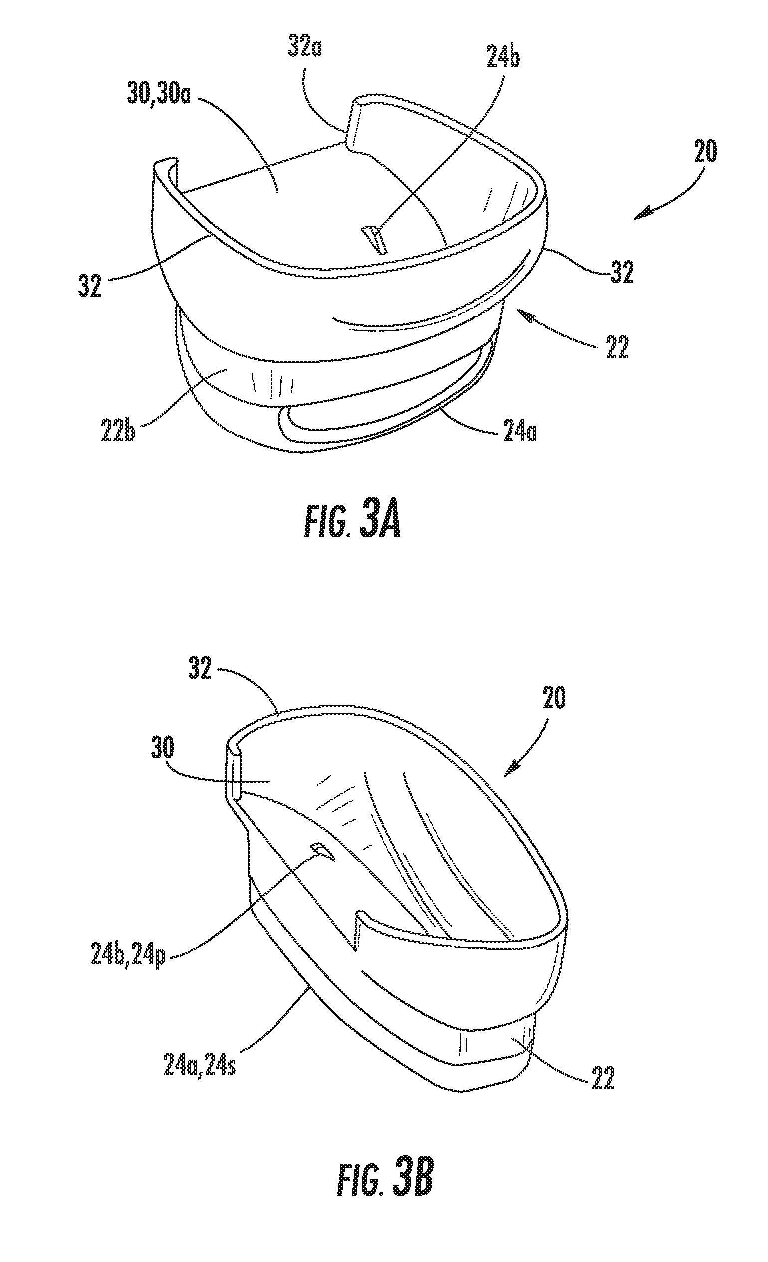
[0049]FIGS. 3A and 3B show a device adapter 20 formed according to a The device adapter 20 can be removably used with the docking base 10 in the battery changing and / or data transferring operation. The device adapter 20 has a main adapter body 22 configured to be supported by the docking base 10. The main adapter body 22 can include a base portion 22b adapted to be supported in the receiving area 12 of the docking base 10, as is shown in FIG. 4. For example, the base portion 22b is fitted and held in the receiving chamber 12a of the docking base 10.

[0050]Additionally or alternatively, the base portion 22b of the device adapter 20 can be formed to have a shape and / or size that prevents the base portion 22b from lateral movement inside the receiving chamber 12a. In one example, the base portion 22b can be formed to have a substantially same but complementary shape of at least part of the receiving area 12 and be immovably held therein until the device adapter 20 is removed from the r...

second embodiment

[0065]FIGS. 6A to 6G show the device adapter 120, in which further details concerning the contact ports, electrical circuit, and electrical contacts of the device adapter 120 are shown and will be described below. As is best shown in FIGS. 6A and 6B, the device adapter 120 has first and second contact ports 124a, 124b, which are electrically connectable to the contact ports in the docking base 10 and the portable electronic device 2 during the battery charging and / or data transfer operation. In one example, the first contact port 124a is formed on the base portion 122b and compatible to those in the contact port 14 on the docking base 10. As one skilled in the art will appreciate, the first contact port 124a can be configured in various forms, such as a USB port, or a female pin-type port for a battery charging and / or data transfer operation.

[0066]The second contact port 124b is formed on the main adapter body 122 of the device adapter 120 for connecting to the device port in the po...

third embodiment

[0080]FIG. 11 shows a device adapter 220 formed according to a In this embodiment, the surrounding wall 222w has straight profile in the axial direction, as best illustrated in FIG. 12.

[0081]FIG. 13 shows a variation of the device adapter 220 in FIG. 11. In this variation, an additional support can be provided to keep the combined portable electronic device 2 and cover case 4 in position during the battery charging and / or data transfer operation. In one example, a supporting wall 332 can be formed on the main adapter body 222 to hold the contact portion of the combined portable electronic device 2 and cover case 4 in place during the battery charging and / or data transfer operation. The supporting wall 332 can be elevated from the main adapter body 222 and positioned to be in contact with the combined portable electronic device 2 and cover case 4 at one or more locations. In the example shown in FIG. 13, the supporting wall 332 is shown as a continuous wall. In another example, the ...


PUM


Abstract

The embodiments disclosed herein relate generally to a docking station for charging batteries used in portable electronic devices and / or for transferring data to or from portable electronic devices. The docking station is adapted to receive a rechargeable battery either directly and / or through its portable electronic device, which can be fitted with or without a cover case. For example, the docking station has a receiving area configured to receive and hold a portable electronic device including a rechargeable battery and / or a rechargeable battery after being removed from the corresponding portable electronic device. The invention also relates to a removable device adapter for use with a docking station to receive a rechargeable battery directly and / or through its portable electronic device fitted with or without a cover case. For example, the device adapter can be removably used in a docking station during a charging operation of a rechargeable battery and / or a data transferring operation of a portable electronic device.

Description

CROSS-REFERENCE TO RELATED APPLICATIONS[0001]This patent application claims priority from U.S. Provisional Patent Application Nos. 61 / 253,318 and 61 / 303,308 filed Oct. 20, 2009 and Feb. 10, 2010, respectively.BACKGROUND OF THE INVENTION[0002]1. Field of the Invention[0003]The invention relates generally to a docking station for charging batteries used in portable electronic devices and / or for transferring data to or from portable electronic devices. More specifically, the invention relates to a docking station adapted to receive a rechargeable battery either directly and / or through its portable electronic device fitted with or without a cover case. The invention also relates to a removable device adapter for use with a docking station to receive a rechargeable battery directly and / or through its portable electronic device fitted with or without a cover case.[0004]2. Description of the Related Art[0005]Various docking stations have been designed for use with portable electronic devic...

Claims


Application Information

Patent Timeline
Patent Type & Authority Applications(United States)
IPC IPC(8): G06F1/16
CPCG06F1/1632H04M1/04H02J7/0044H02J7/0027H01R31/06H02J7/00H02J2310/22
Inventor SA, SHUANG
Owner UNKNOWN
Why Eureka
Try Eureka