Method of Fabricating LCD Panel

a technology of liquid crystal display panel and fabrication method, which is applied in the direction of lamination ancillary operations, instruments, chemistry apparatus and processes, etc., can solve the problems of inability to accurately perform such processes, additional cost to purchase specific machines, and exposure damage of liquid crystal molecules, etc., to achieve reduced ultraviolet exposure, reduced cost, and simple process

Inactive Publication Date: 2011-06-16
HSU CHEMING
View PDF1 Cites 0 Cited by
  • Summary
  • Abstract
  • Description
  • Claims
  • Application Information

AI Technical Summary

Benefits of technology

[0012]A method of fabricating a liquid crystal display panel is provided in the present invention. By using a one-drop-filling method, a liquid crystal material is injected between two parallel substrates with a signal input exposed. A voltage is applied to the signal input terminal and a ultra-violet beam is radiating, such that the monomers in the liquid crystal material are polymerized to form stabilized liquid crystal molecules and photo-cure a sealant between the substrates. As the ultra-violet radiation is applied only once, the damage caused thereby is suppressed. In addition, the simplified process provides better viewing angle of the liquid crystal display panel.
[0015]By the above fabrication process, the polymer-stabilization of the liquid crystal and photo-cure process are synchronously performed. By a subsequent light-on inspection process can be performed on the signal input terminal formed by the same fabrication process to scan signal. Thereby, the ultra-violet exposure is minimized, and the damage of liquid crystal molecules caused thereby is suppressed. A better liquid crystal display panel is thus provided with simpler process and reduced cost.

Problems solved by technology

In brief, although the above one-drop-filling liquid crystal fabrication process and the polymer-stabilized liquid crystal fabrication process simplify the process and provide a fast response of the liquid crystal display panel, additional cost is required to purchase the specific machine to perform such process.
Further, as two ultra-violet radiations are applied to the liquid crystal molecules, the exposure damage of the liquid crystal molecules is inevitable.

Method used


Image

  • Method of Fabricating LCD Panel
  • Method of Fabricating LCD Panel
  • Method of Fabricating LCD Panel

Examples


Embodiment Construction

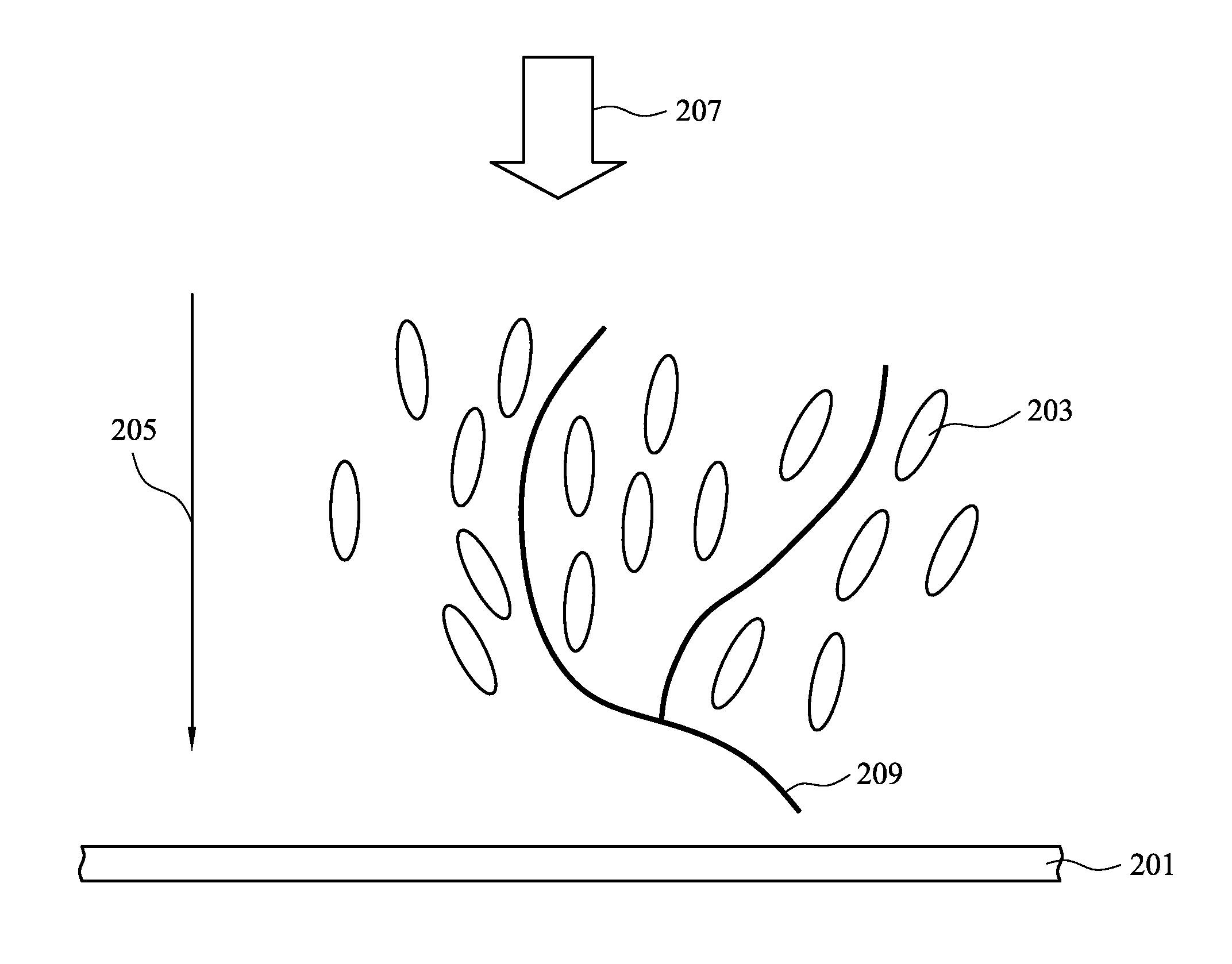
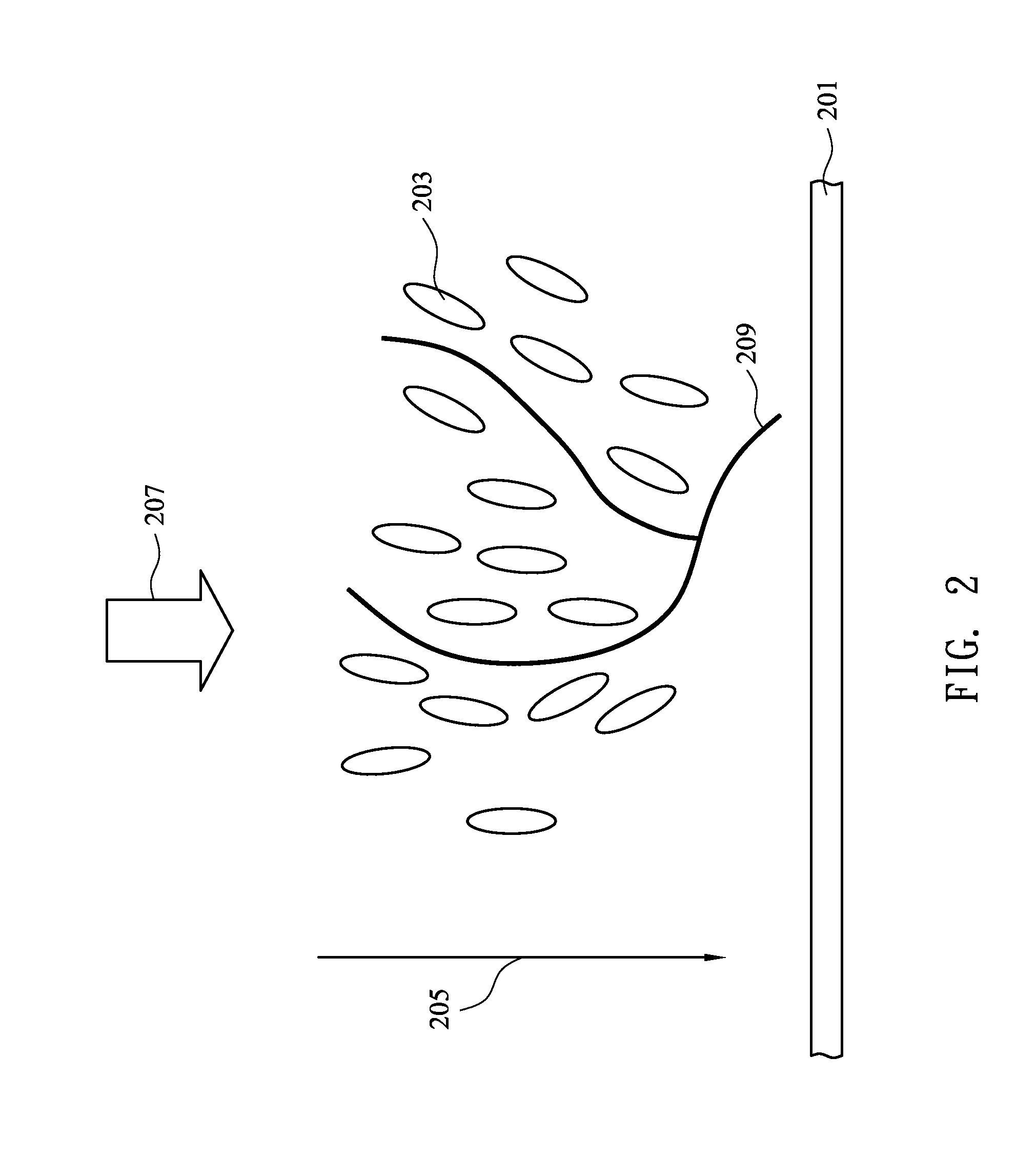
[0023]A method of fabricating a liquid crystal display of the present invention is provided by using a one-drop-filling (ODF) method to inject liquid crystal material between two parallel substrates, while a signal input terminal on the substrate is exposed. A voltage and ultra-violet radiation are applied to the signal input terminal synchronously, such that the monomers can be polymerized to stabilize the liquid crystal molecules and to photo-cure a sealant. Thereby, the damage of liquid crystal molecules caused ultra-violet radiation is minimized and the fabrication process is simplified. Detailed description of the process of the present invention can be referred to FIGS. 4 and 5.

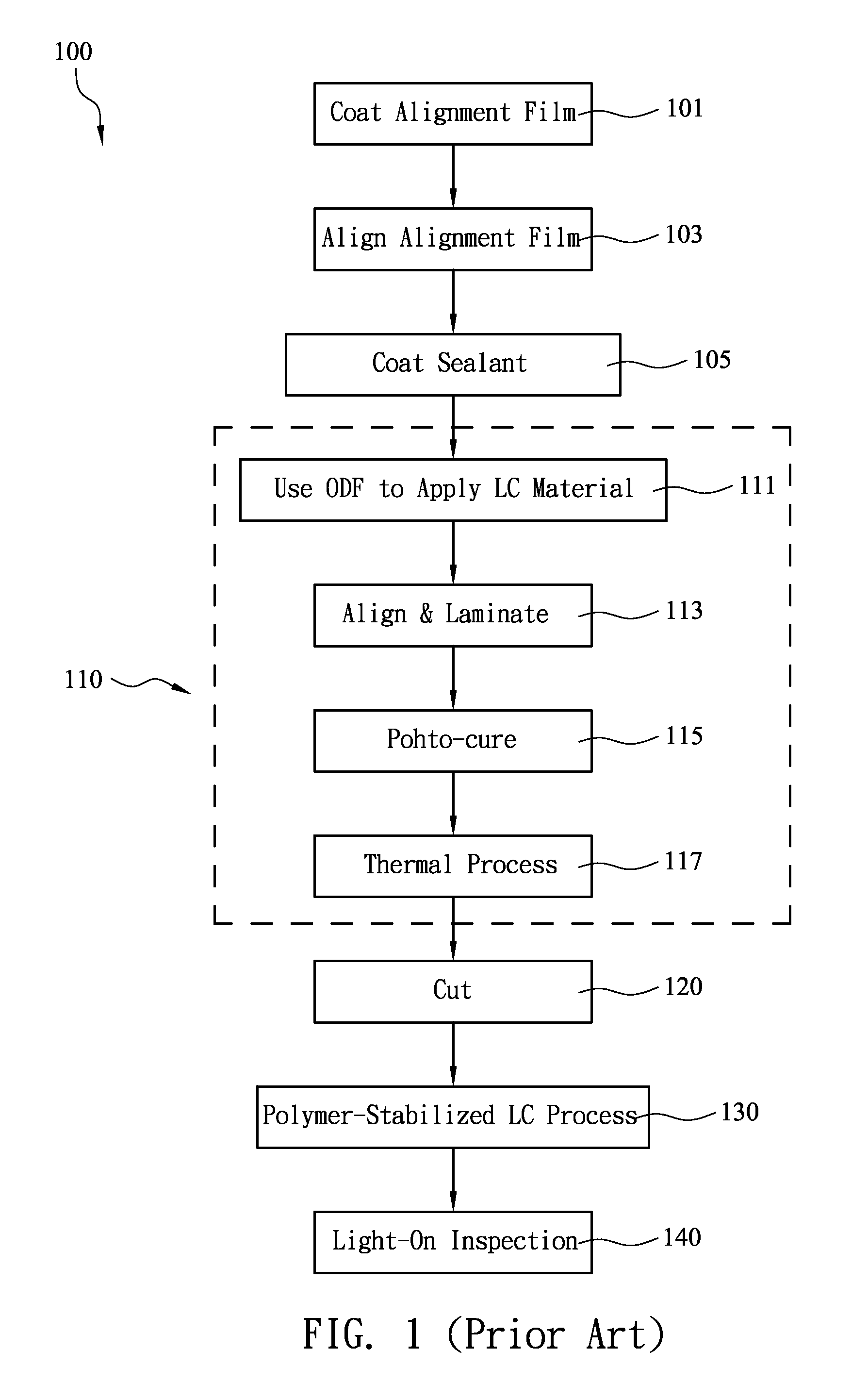
[0024]In FIG. 4, an embodiment of fabricating a liquid crystal display panel is illustrated. As shown, the fabrication process 400 includes a step 401 for coating an alignment film on each of the substrates comprising the thin-film transistor array and the color filter. In one embodiment, the thin-film ...


PUM

PropertyMeasurementUnit
voltageaaaaaaaaaa
voltageaaaaaaaaaa
voltageaaaaaaaaaa

Abstract

A method of fabricating a liquid crystal display, using one-drop-filling (ODF) method to inject liquid crystal material between two parallel substrates, while a signal input terminal on the substrate is exposed. A voltage and ultra-violet radiation are applied to the signal input terminal synchronously, such that the monomers can be polymerized to stabilize the liquid crystal molecules and to photo-cure a sealant. Thereby, the damage of liquid crystal molecules caused ultra-violet radiation is minimized, the fabrication process is simplified, and the cost of process equipment is reduced.

Description

CROSS-REFERENCE[0001]This application is a divisional application of U.S. patent application Ser. No. 11 / 149,136, filed on Jun. 10, 2005.BACKGROUND OF THE INVENTION[0002]1. Field of Invention[0003]The present invention relates in general to a method of fabricating a liquid crystal display panel with improved polymer-stabilized liquid crystal (PSLC).[0004]2. Related Art[0005]Polymer-stabilized liquid crystal (PSLC) is an improve liquid crystal mode used for enhancing response speed. Referring to FIG. 1, a process for assembling a conventional liquid crystal cell is illustrated. In step 100, two substrates with a thin-film transistor array (TFT array) and a color filter are prepared. In step 101, alignment films are coated on two substrates. In step 103, alignment is performed on the alignment films. In step 105, the sealant coating is performed, that is, the sealant is applied to the substrate on which the thin-film transistor array or the color filter is formed.[0006]Steps 111 to 11...

Claims


Application Information

Patent Timeline
Patent Type & Authority Applications(United States)
IPC IPC(8): B32B38/04B32B38/00B32B37/14B32B37/02
CPCG02F1/1339G02F2001/13775G02F2001/13415G02F1/1341G02F1/13415G02F1/13775
Inventor HSU, CHEMING
Owner HSU CHEMING
Why Eureka
Try Eureka