Method of determining end member concentrations

a technology of end members and concentrations, applied in survey, earth-moving drilling, borehole/well accessories, etc., can solve the problems of limiting the general application of known geochemical fingerprinting techniques for production allocation, complex tool runs for downhole sampling, and high cost, so as to reduce the number of tool runs through the well, the effect of reducing costs and risks

Active Publication Date: 2011-06-16
SCHLUMBERGER TECH CORP
View PDF10 Cites 17 Cited by
  • Summary
  • Abstract
  • Description
  • Claims
  • Application Information

AI Technical Summary

Benefits of technology

[0011]Accordingly, the present invention provides a method for production allocation by geochemical fingerprinting without the collection of end member samples of the geomarkers to be used, and hence offers a significant advantage over conventional methods.
[0012]The method is best performed using a tool combining flow measuring and sampling capabilities thus reducing the number of tool runs through the well to one thus significantly decreasing costs and risks associated with downhole logging operations, particularly when compared to the conventional sampling of end member samples.

Problems solved by technology

It is a challenge in the oilfield industry to back allocate the contributions of each source from a downstream point of measurement at which the flow is already commingled.
Tool runs for downhole sampling are complex, expensive and may not be feasible in many scenarios, and therefore limit the general application of the known geochemical fingerprinting techniques for production allocation.

Method used


Image

  • Method of determining end member concentrations
  • Method of determining end member concentrations
  • Method of determining end member concentrations

Examples


Embodiment Construction

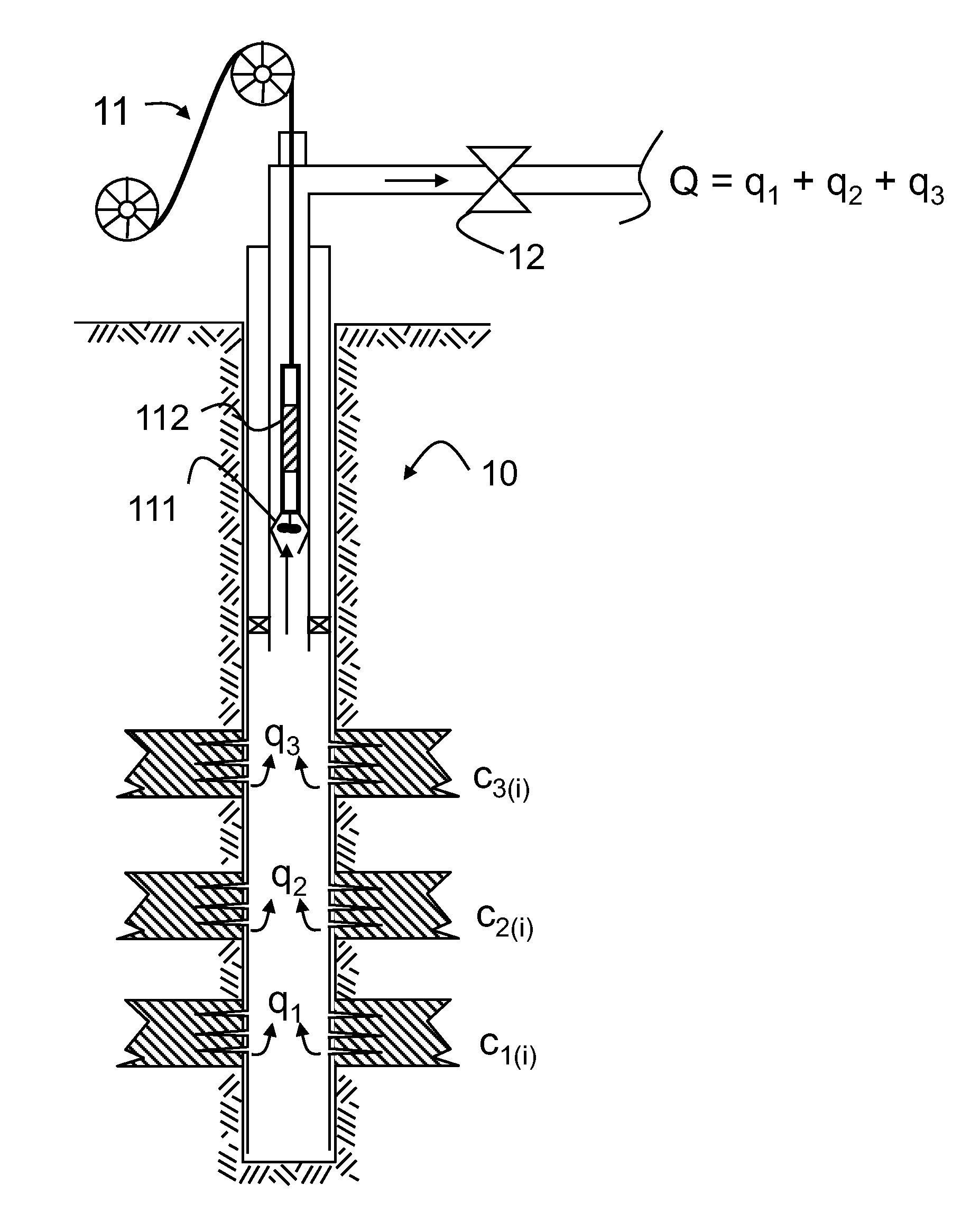
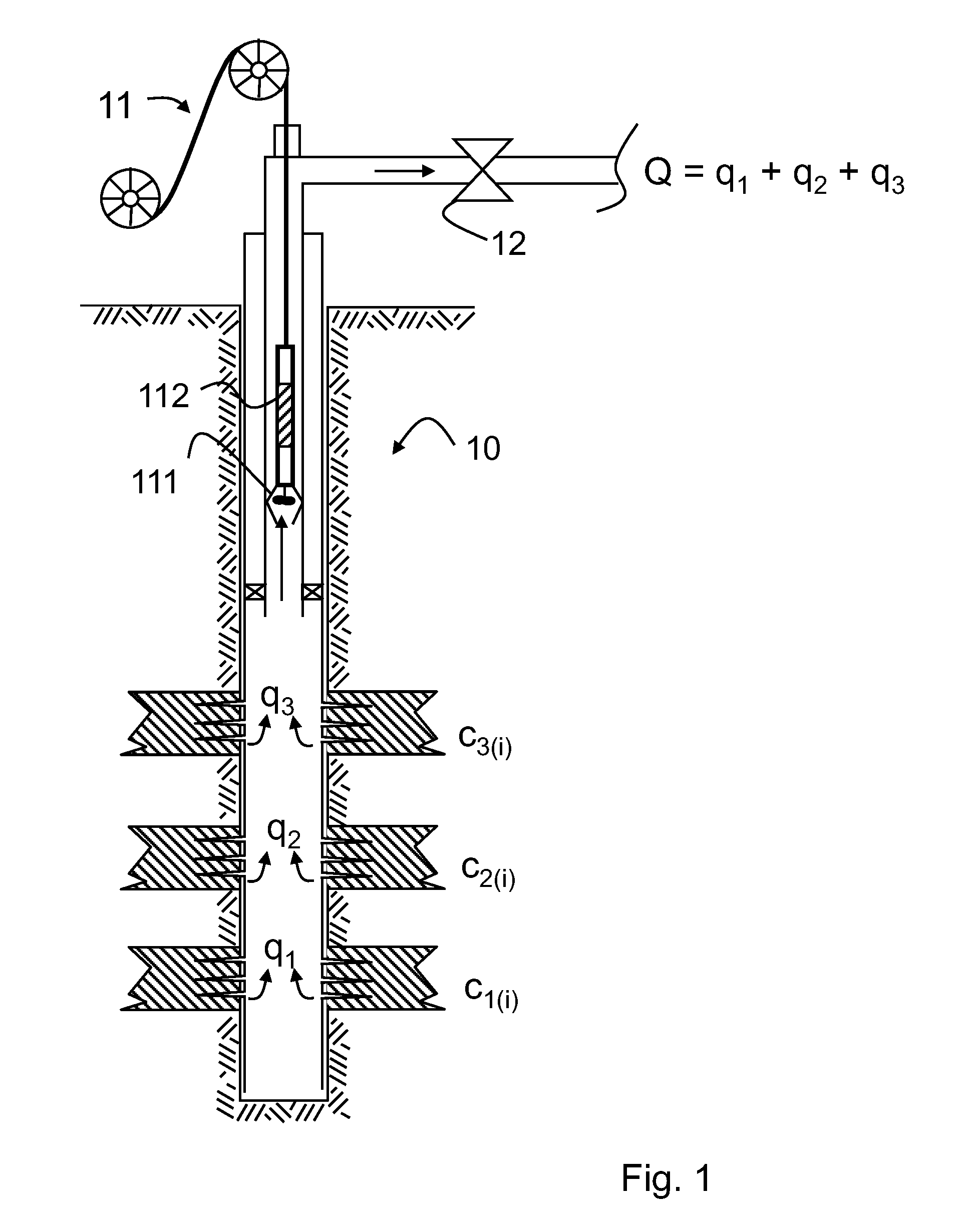
[0022]The method is illustrated by the following example, in which FIG. 1 shows an oil well 10 drilled in a formation containing several oil-bearing layers. In this example, the number of separate layers is chosen to be three to allow for a clearer description of elements of the present invention. However, the number of layers can vary and the below described example is independent of any specific number of layers.

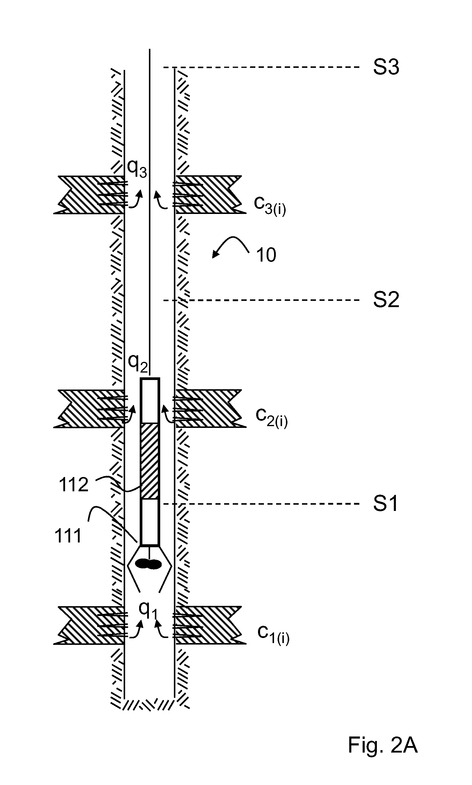
[0023]In the example, there is assigned to each layer a flow rate q1, q2, and q3 , respectively. The fluids produced from the three layers contain chemical components at the so-called end member concentrations c1i, c2i and c3i, respectively, wherein the index number i denotes a specific component i in the fluid.

[0024]In the present example, the component i stands for any component or species being part of the flow stemming from the respective zone. Any such component can be selected as geomarker for later application of a back allocation through fingerprinting. It will be ...


PUM


Abstract

A method of determining a concentration of a component in a flow from a single source or layer contributing to a total flow using the steps of measuring the total flow rate at various depths and sampling the total flow at a depth between two successive sources, measuring a total concentration of one or more flow components within the total flow, repeating the measuring of the total flow rate, the sampling and total concentration in further intervals separating other pairs of successive sources, and determining the concentration of at least one component by solving a system of mass balance equations representing the total flow of the flow components at each sampling depth.

Description

FIELD OF THE INVENTION[0001]The invention relates to methods of determining the end member concentrations of flow components from sources or zones contributing to a total production flow and / or allocating the relative contributions of two or more distinct sources in a well or several wells to the total flow based on compositional analysis or compositional fingerprinting.BACKGROUND[0002]In hydrocarbon exploration and production there is a need to analyze the composite production flow from a well or a group of wells in order to investigate their origin and properties. The production system of a developed hydrocarbon reservoir includes typically pipelines which combine the flow of several sources. These sources can be for example several wells or several producing zones or reservoir layers within a single well. It is a challenge in the oilfield industry to back allocate the contributions of each source from a downstream point of measurement at which the flow is already commingled.[0003...

Claims


Application Information

Patent Timeline
Patent Type & Authority Applications(United States)
IPC IPC(8): E21B49/08E21B47/00
CPCE21B49/08E21B47/10
Inventor ZIAUDDIN, MURTAZAKARACALI, OZGUR
Owner SCHLUMBERGER TECH CORP
Why Eureka
Try Eureka