Ldp extension for forwarding path congestion notification

Active Publication Date: 2011-06-16
VERIZON PATENT & LICENSING INC
View PDF8 Cites 36 Cited by
  • Summary
  • Abstract
  • Description
  • Claims
  • Application Information

AI Technical Summary

Problems solved by technology

This can cause traffic congestion on the MPLS-TP if

Method used


Image

  • Ldp extension for forwarding path congestion notification
  • Ldp extension for forwarding path congestion notification
  • Ldp extension for forwarding path congestion notification

Examples


Embodiment Construction

[0013]The following detailed description refers to the accompanying drawings. The same reference numbers in different drawings may identify the same or similar elements. Also, the following detailed description does not limit the invention.

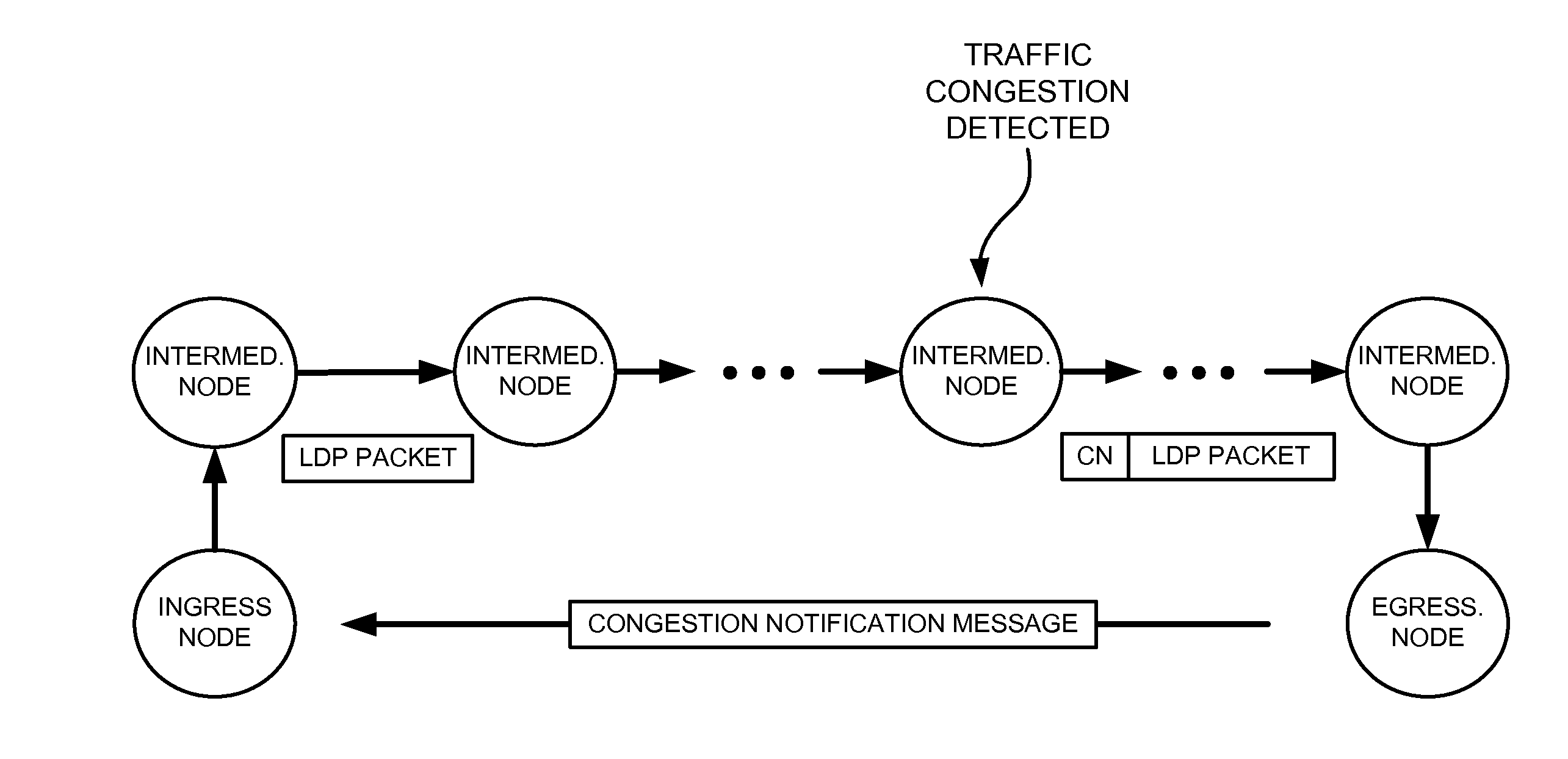
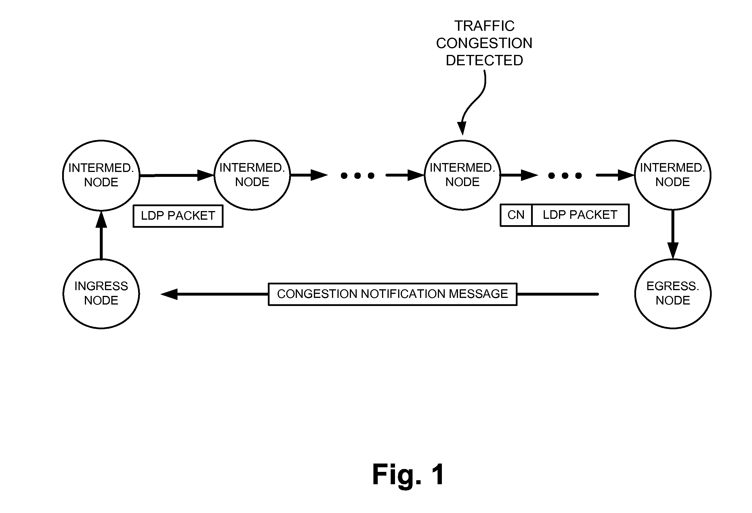
[0014]An implementation, described herein, may provide an LDP extension that facilitates congestion notification in an MPLS network. For example, a node, which detects congestion on an LSP, may add an indicator of traffic congestion to LDP packets that the node transmits on the LSP. An egress node, that receives an LDP packet with an indicator of traffic congestion, may identify the ingress node associated with the LSP and send, to the ingress node, a congestion notification message so that the ingress node may determine whether to pre-empt the LDP packet flow.

[0015]FIG. 1 is a diagram of an overview of an implementation described herein. As shown in FIG. 1, assume that an LSP in a network includes an ingress node, a set of intermediate nodes, and...


PUM


Abstract

A system includes an ingress node, an egress node, and one or more intermediate nodes. A path is formed from the ingress node to the egress node via the one or more intermediate nodes, where the path carries label distribution protocol (LDP) packets of an LDP traffic flow. One of the intermediate nodes detects traffic congestion, modifies one of the LDP packets to include an indicator of the traffic congestion, and sends the modified LDP packet towards the egress node. The egress node receives the modified LDP packet and notifies the ingress node of the traffic congestion in response to identifying the indicator of the traffic congestion within the modified LDP packet.

Description

BACKGROUND INFORMATION[0001]The label distribution protocol (LDP) is a protocol used to distribute labels in a multiprotocol label switching (MPLS) environment. LDP relies on the underlying routing information to forward label packets. LDP is used for signaling best-effort label switched paths (LSPs). LDP has no traffic engineering capability. In other words, LDP has no concept of bandwidth or congestion.[0002]The industry is gradually moving towards the direction of converged packetized optical networks using MPLS transport profile (MPLS-TP), such as generalized MPLS (GMPLS). MPLS-TP uses the resource reservation protocol—traffic engineering (RSVP-TE) signaling protocol to set up LSPs. MPLS-TP LSPs are traffic engineering capable (e.g., include concepts of bandwidth and congestion). MPLS-TP LSPs are the transport layer LSPs and carry all types of traffic, including upper layers, such as MPLS RSVP-TE traffic (which is traffic engineering capable) and LDP traffic (which is not traffi...

Claims


Application Information

Patent Timeline
IPC IPC(8): H04L12/56
CPCH04L45/507H04L47/11H04L47/33H04L47/26H04L47/32H04L47/18H04L47/267H04L47/265
Inventor SO, NING
Owner VERIZON PATENT & LICENSING INC
Why Eureka
Try Eureka