Video encoding method and video decoding method

a video and encoding technology, applied in the field of encoding a video, can solve the problems of overhead and affect and achieve the effect of reducing the amount of coded bits and improving the efficiency of compression

Active Publication Date: 2011-06-16
MAXELL HLDG LTD
View PDF8 Cites 94 Cited by
  • Summary
  • Abstract
  • Description
  • Claims
  • Application Information

AI Technical Summary

Benefits of technology

[0008]According to the present invention, it is possible to reduce the amount of coded bits for a motion vector and improve the efficiency of compression.

Problems solved by technology

Thus, an overhead may affect the amount of coded bits.

Method used


Image

  • Video encoding method and video decoding method
  • Video encoding method and video decoding method
  • Video encoding method and video decoding method

Examples


first embodiment

[0040]FIG. 7 is a conceptual diagram showing an example of the predictive motion vector calculating method according to the present embodiment. In FIG. 7, vectors that are candidates for a predictive motion vector are vectors (of three types) of blocks A, B and C. The block A is located on the left side of a target block. The block B is located on the upper side of the target block. The block C is located on the upper right side of the target block. In this case, a motion vector of the block A is indicated by MVA; a motion vector of the block B is indicated by MVB; and a motion vector of the block C is indicated by MVC.

[0041]First, x and y components of the motion vectors MVA, MVB and MVC are aligned. A distribution of the motion vectors is examined using a threshold Thre1 on the basis of four types of cases CASE1 to CASE4. In FIG. 7, the directions of arrows are directions in which the components (of the motion vectors) that have large values extend. Among the x and y components of...

second embodiment

[0082]A second embodiment of the present invention is described below.

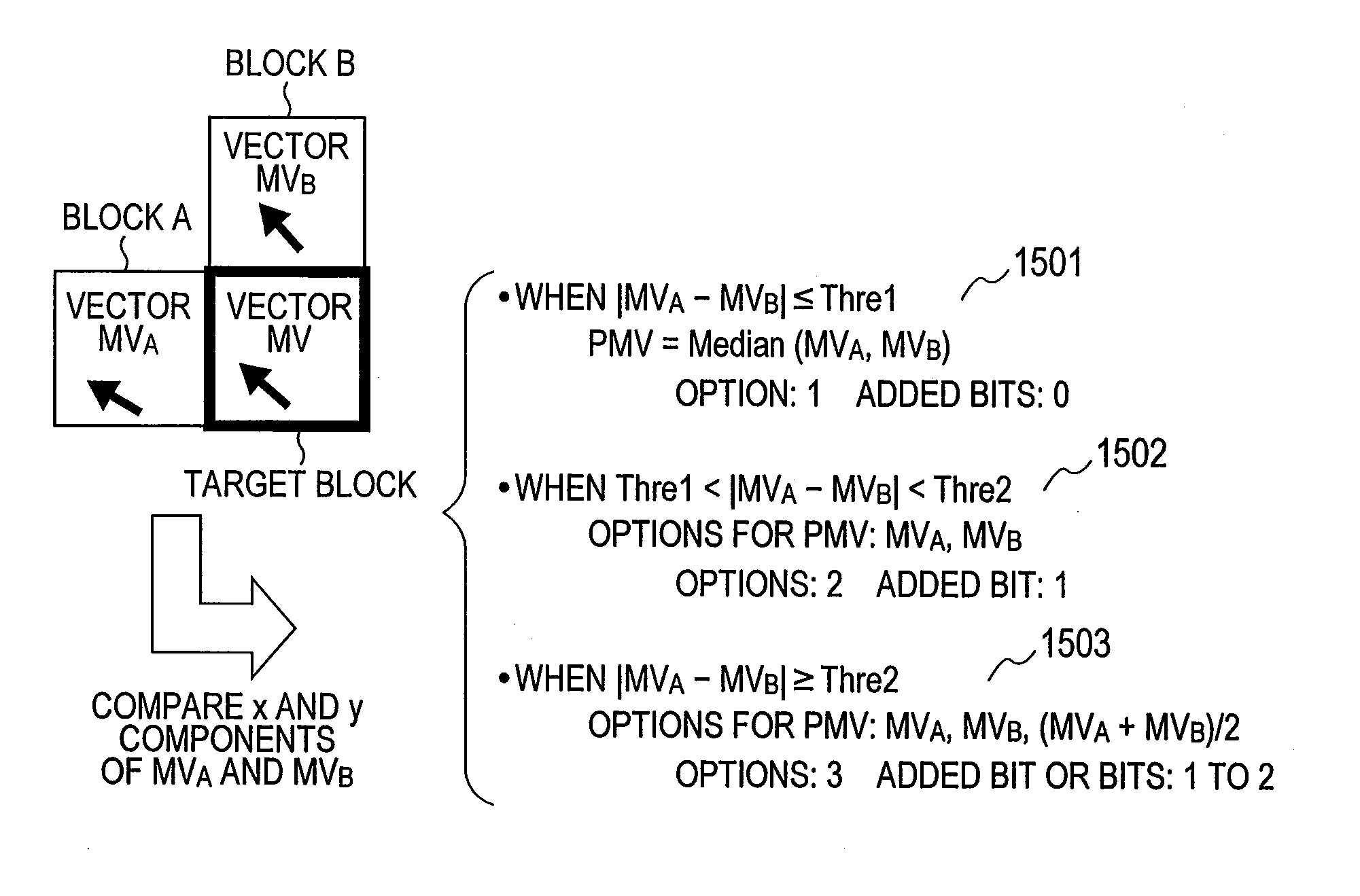
[0083]In the first embodiment, the number of vectors used as candidate of predictive motion vectors is three. In the second embodiment, as a simpler method, the number of vectors used as candidate of predictive motion vectors is two.

[0084]A video encoding device according to the second embodiment is different from the video encoding device (shown in FIGS. 1 and 2) according to the first embodiment only in the method for calculating a predictive motion vector PMV. Thus, other configurations and operations of the video encoding device according to the second embodiment are described above in detail, and a description thereof is omitted.

[0085]In addition, a video decoding device according to the second embodiment is different from the video decoding device (shown in FIGS. 3 and 4) according to the first embodiment only in the method for calculating a predictive motion vector PMV. Thus, the other configurations and op...


PUM


Abstract

Provided is a video encoding / decoding technique for improving the compression efficiency by reducing the motion vector code amount. In a video decoding process, the prediction vector calculation method is switched from one to another in accordance with a difference between predetermined motion vectors among a plurality of motion vectors of a peripheral block of a block to be decoded and already decoded. The calculated prediction vector is added to a difference vector decoded from an encoded stream so as to calculate a motion vector. By using the calculated motion vector, the inter-image prediction process is executed.

Description

TECHNICAL FIELD[0001]The present invention relates to a technique for encoding a video (dynamic image) and a technique for decoding a video (dynamic image).BACKGROUND ART[0002]As a method for digitalizing, recording and transmitting a large amount of video information, encoding formats such as Moving Picture Experts Group (MPEG) have been established. For example, MPEG-1 format, MPEG-2 format, MPEG-4 format H.264 / Advanced Video Coding (AVC) format and the like have been established as international standard encoding formats. These formats are used for digital satellite broadcasting, digital versatile discs (DVD), mobile phones, digital cameras and the like as encoding formats. The range of use of the formats has been expanded, and the formats are more commonly used.[0003]According to the formats, an image to be encoded is predicted on a block basis using information on an encoded image, and the difference (prediction difference) between an original image and the predicted image is e...

Claims


Application Information

Patent Timeline
Patent Type & Authority Applications(United States)
IPC IPC(8): H04N7/32H04N19/50H04N19/12H04N19/13H04N19/134H04N19/139H04N19/146H04N19/147H04N19/154H04N19/196H04N19/423H04N19/46H04N19/463H04N19/503H04N19/51H04N19/513H04N19/52H04N19/593H04N19/61H04N19/625H04N19/63H04N19/70H04N19/91
CPCH04N19/52H04N19/51H04N19/513H04N19/00721H04N19/61H04N19/517H04N19/577H04N19/13G06F3/0604G06F3/0655G06F3/0673G06N3/04G06N3/10H04N19/172H04N19/176H04N19/184
Inventor TAKAHASHI, MASASHIYAMAGUCHI, MUNEAKI
Owner MAXELL HLDG LTD
Why Eureka
Try Eureka