
Storage region management method, storage region allocation method and program

a storage region and management method technology, applied in the field of storage region management, can solve the problems of ineffective utilization of memory space and unusable areas, and achieve the effect of effective management and effective utilization of storage areas

Active Publication Date: 2011-06-16
YOSHIOKA MAKOTO
View PDF0 Cites 10 Cited by
  • Summary
  • Abstract
  • Description
  • Claims
  • Application Information

AI Technical Summary

Benefits of technology

[0028]Whereat, this invention has the objective of providing an art that enables the management of remaining storage areas even when an area that is not a power-of-2 size is obtained from a power-of-2 size area or even when a power-of-2 size area is obtained from an area that is not a power-of-2 size and that effectively utilizes storage areas.
[0032]Because, in accordance with this invention, storage areas are managed by a combination of power-of-2 sizes, storage areas with any size can be effectively managed, and because allocation management is performed for storage areas that have been partitioned into each power-of-2 size, and because files and memory objects are allocated in continuous storage areas with no waste, effective utilization of storage areas can be expected.

Problems solved by technology

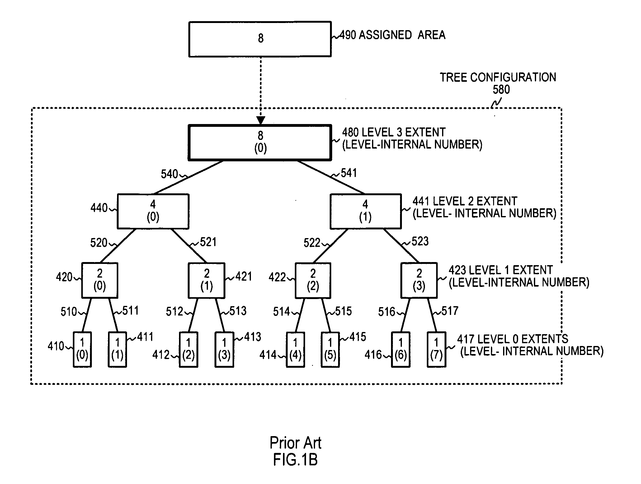
However because memory area is allocated in units of the power of 2 in the buddy system, when, for example, a file of 2.1 GB is to be allocated, an area of 4 GB is necessary and after the file allocation an unused area in which no data is written exists in the area of 4 GB but previous file systems are not able to use the unused area for another file allocation and thus memory space cannot be used effectively.
However, because there is no management of the area left over from an initial power-of-2 size area when an area that is not a power-of-2 size is allocated in the initial area or of the area left over from an initial area that is not a power-of-2 size when an area with a power-of-2 size is allocated in that initial area, the problem exists that these areas are not utilized effectively.

Method used


Image

  • Storage region management method, storage region allocation method and program
  • Storage region management method, storage region allocation method and program
  • Storage region management method, storage region allocation method and program

Examples


embodiment 1

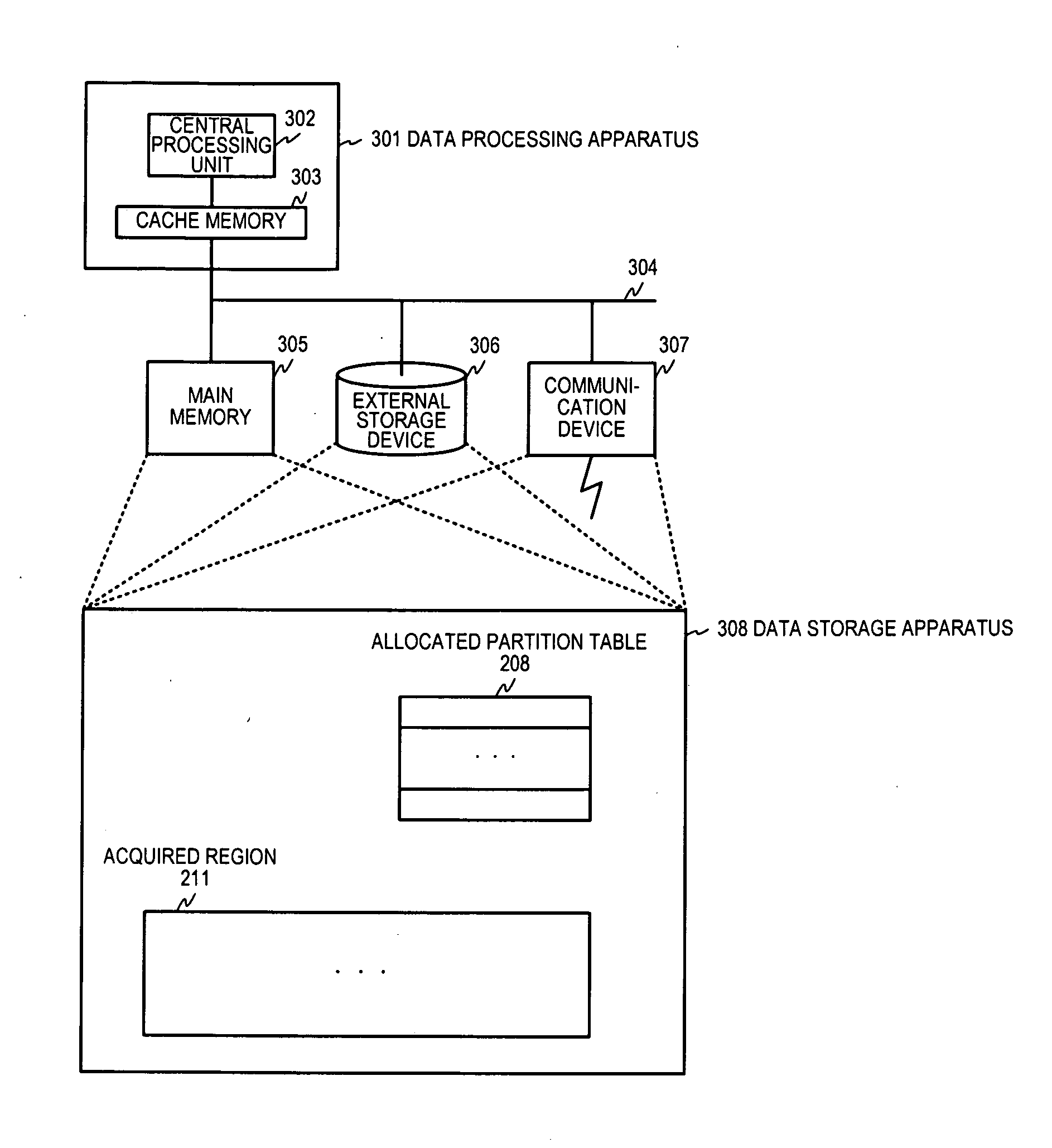
[0069]Hereinbelow, preferred embodiment 1 of this invention is described referencing FIG. 3A to FIG. 3C. This preferred embodiment acquires the allocation size for a region, and computes a sum of mutually differing powers of 2 from the allocation size, and the region undergoes a primary partition into primary segments whose sizes are the computed mutually differing powers of 2 and is managed for each of the primary segments that are the result of the primary partition. There is no restriction on the method to acquire regions, and, as was noted above, they can be acquired by means of the above noted unshown utility program like a disk allocator or other such means, and it is sufficient to be provided the start position of a region and its size.

[0070]FIG. 3A is a drawing describing an overview of the primary partitioning (initial allocation) of an acquired region and its management in preferred embodiment 1 of this invention.

[0071]The example in FIG. 3A shows the relationship between ...

embodiment 2

[0088]FIG. 4A is a drawing describing an overview of the acquisition of a segment with the requested allocation size, and releasing unused segments in preferred embodiment 2 of this invention.

[0089]FIG. 4A shows the relation between requested allocation size 20a, which is not equal to a power-of-2 size, and the segment 80 that is acquired based on that allocation size, and the relations among the segments 1 to 4 (81b, 83b, 84c, 82c) that are multilevel-partitioned out of the acquired segment 80. The significant bit positions in requested allocation size 20a are bits 3 and 1, and thus the requested allocation size is 2 to the 3rd power plus 2 to the 1st power=10.

[0090]If a plurality of significant bits exist, in other words, if the requested allocation size is not a power-of-2 size, one position higher than the highest order significant bit position 3 in requested allocation size 20a, that is, the position 4, becomes the allocated partition level 44a.

[0091]Then, as shown by the dott...

embodiment 3

[0178]FIG. 10 is a drawing showing an example of the detailed flow in step S904 shown in FIG. 9 and it describes an example of the processing flow for acquiring an available extent in preferred embodiment 3 of this invention. The example of processing flow shown in FIG. 10 is one that corresponds to the processing flow for preferred embodiment 2 of this invention shown in FIG. 5B.

[0179]As shown in the drawing, first, in step S1022, an extent with an available status is sought for within the partition level. The partition level is the one set at step S900 or step S907a shown in FIG. 9. Next, at step S1023, a determination is made whether any available extent exists in the partition level. If there is no available extent, the acquisition is taken to be a failure and processing is terminated.

[0180]Conversely, if the determination at step S1023 is that there is an available extent at the partition level, processing proceeds to step S1026, and an allocation number with an available statu...


PUM


Abstract

A storage area management method for a data storage apparatus partitions an acquired storage area into storage areas with differing power-of-2 sizes and manages each of them. Also, a storage area allocation method receives an allocation request for a storage area that includes a requested allocation size, and acquires an available storage area whose size is the smallest power-of-2 size encompassing the requested allocation size, and obtains a binary expression of the requested allocation size, and in response to the received allocation request, allocates a contiguous storage area comprised of storage areas each of whose size is a power of 2 of a value of a bit position wherein a 1 is set in the binary expression.

Description

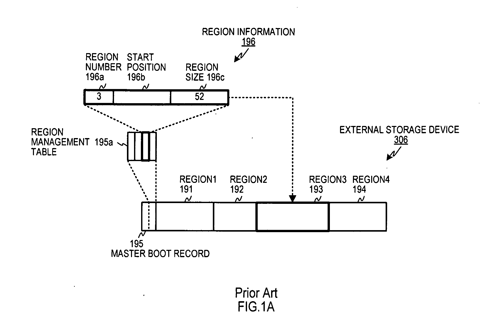
CROSS-REFERENCE TO RELATED APPLICATIONS[0001]This application is a continuation of PCT / JP2009 / 003452 filed on Jul. 22, 2009, and is based on and claims the benefit of priority of the prior Japanese Patent Application Nos. 2008-209395 and 2008-264689, filed on Aug. 17, 2008 and Oct. 11, 2008 respectively, the entire contents of which are incorporated herein by reference. The contents of PCT / JP2009 / 003452 are incorporated herein by reference in their entirety.BACKGROUND OF THE INVENTION[0002]1. Field of the Invention[0003]This invention is related to technology for managing storage areas in a storage device and allocating files and memory objects to those storage areas.[0004]2. Description of Related Art[0005]Up to now, file systems such as, for example, FAT (File Allocation Tables) or NTFS (NT File System) have been used as the method to manage data stored in a storage device like a hard disk and so forth.[0006]FIG. 1A is a drawing describing the region allocation for an external sto...

Claims


Application Information

Patent Timeline
Patent Type & Authority Applications(United States)
IPC IPC(8): G06F12/02
CPCG06F3/0608G06F12/04G06F3/0674G06F3/0644G06F12/06G06F12/0253G06F12/023G06F3/0604G06F3/0631G06F3/0673
Inventor YOSHIOKA, MAKOTOKOKUBUN, MITSUHIROSHINJO, TOSHIOSHINJO, KOUTARO
Owner YOSHIOKA MAKOTO
Learn More