Shock absorber

a technology of shock absorber and flexible disk, which is applied in the direction of shock absorber, damper-spring combination, liquid-based damper, etc., can solve the problems of inability to obtain desired damping force characteristics and high pressure in the back-pressure chamber, and achieve the effect of limiting the deflection of the flexible disk member

Active Publication Date: 2011-06-23
HITACHI ASTEMO LTD
View PDF3 Cites 19 Cited by
  • Summary
  • Abstract
  • Description
  • Claims
  • Application Information

AI Technical Summary

Benefits of technology

[0013]A stopper may be provided downstream of the flexible disk member to limit an amount of deflection of the flexible disk member.

Problems solved by technology

The shock absorber, in which the valve opening of the main valve is controlled by the pressure in the back-pressure chamber, as disclosed in Japanese Patent Application Publication No. 2006-10069, suffers, however, from the following less useful aspect.
Therefore, when the main valve opens, the pressure in the back-pressure chamber is likely to increase excessively, making it impossible to obtain desired damping force characteristics.

Method used


Image

  • Shock absorber
  • Shock absorber
  • Shock absorber

Examples


Embodiment Construction

[0022]One embodiment of the present invention will be explained below in detail with reference to the accompanying drawings.

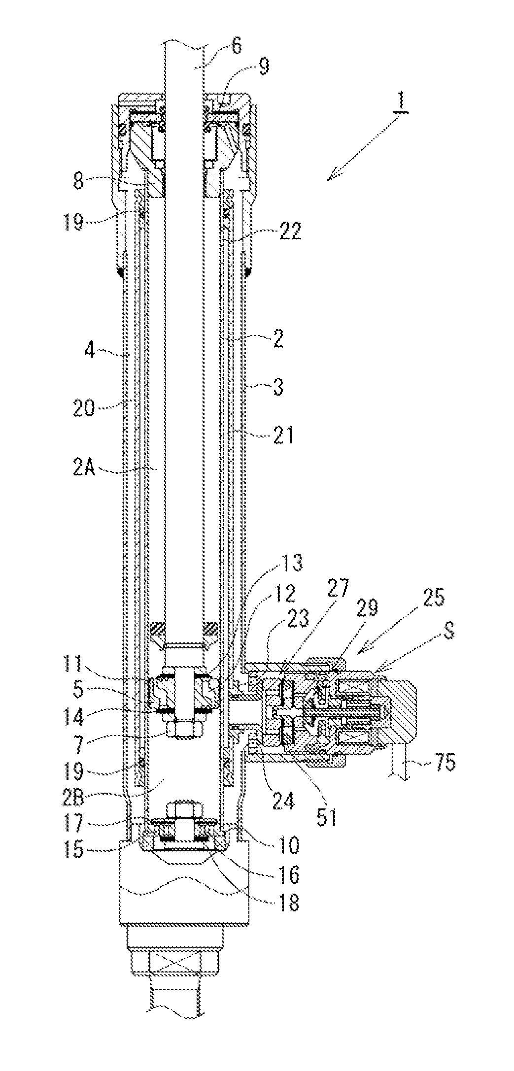
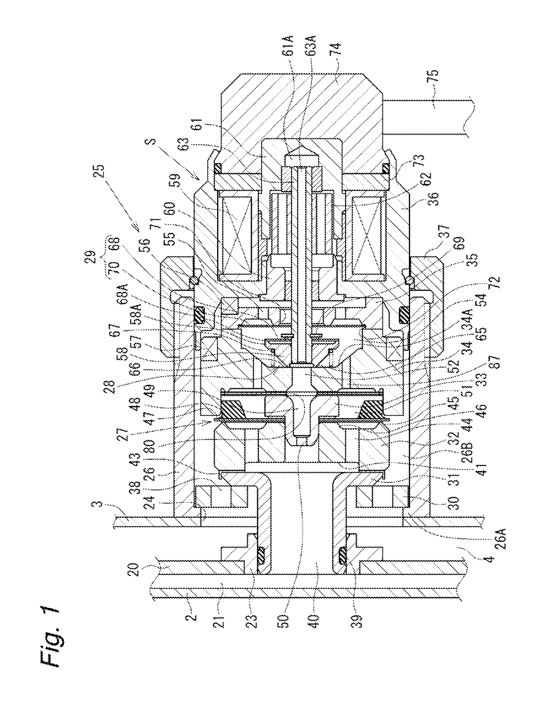
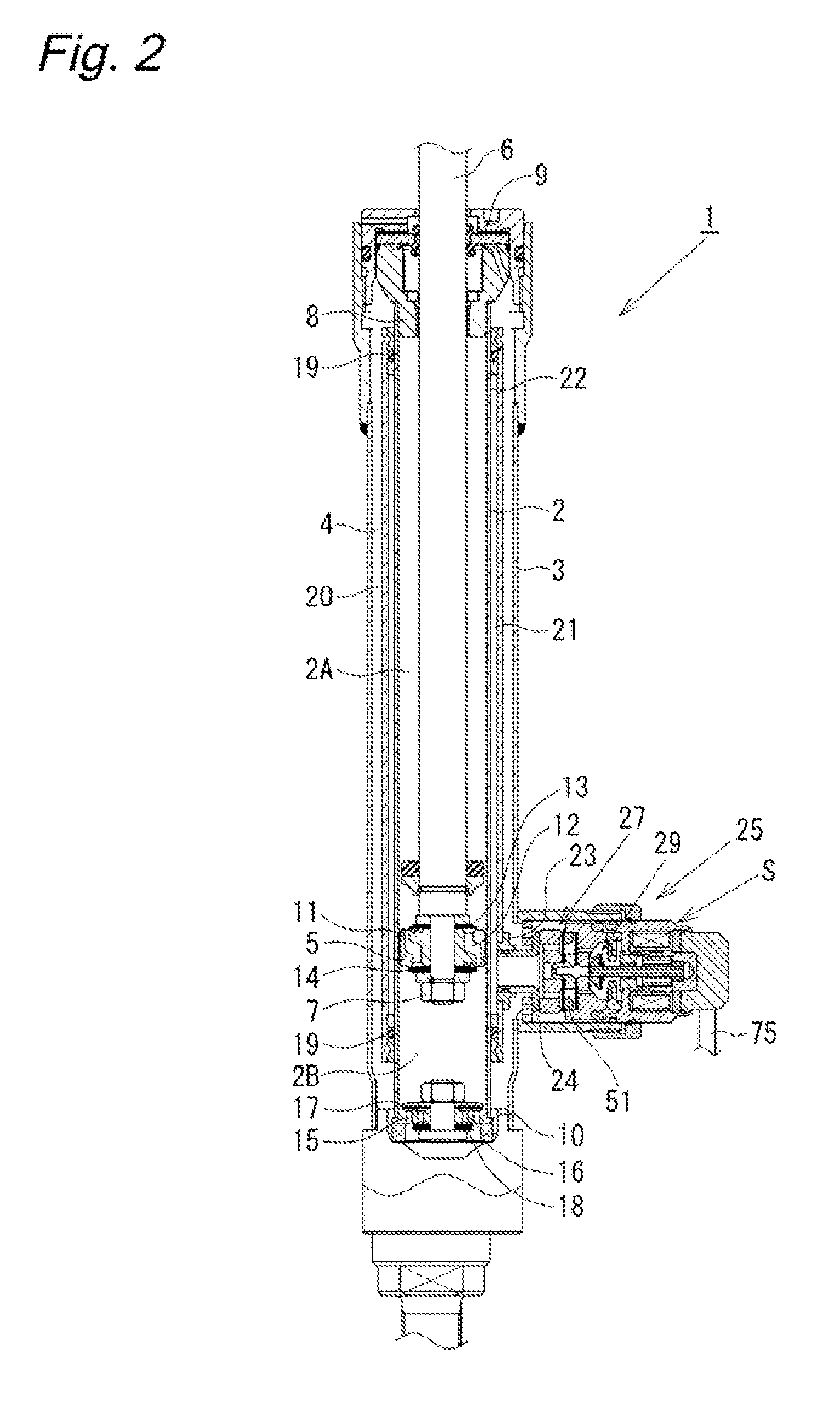
[0023]As shown in FIG. 2, a damping force control type shock absorber 1, which is a shock absorber according to this embodiment, has a dual-tube structure comprising a cylinder 2 and an outer tube 3 provided outside the cylinder 2. A reservoir 4 is formed between the cylinder 2 and the outer tube 3. A piston 5 is slidably fitted in the cylinder 2. The piston 5 divides the interior of the cylinder 2 into two chambers, i.e. a cylinder upper chamber 2A and a cylinder lower chamber 2B. The piston 5 is connected with one end of a piston rod 6 by a nut 7. The other end portion of the piston rod 6 extends through the cylinder upper chamber 2A and further through a rod guide 8 and an oil seal 9, which are fitted to the upper end portion of the double-tube structure comprising the cylinder 2 and the outer tube 3, and projects to the outside of the cylinder 2. A base val...


PUM


Abstract

The flow of hydraulic fluid induced by sliding movement of a piston in a cylinder is controlled by a pilot-type main valve and a pilot valve to generate damping force. The valve opening of the main valve is controlled by adjusting the pressure in a pilot chamber through the pilot valve. A volume compensating chamber is defined by a flexible disk member so as to face the pilot chamber. The volume compensating chamber is communicated with a reservoir through communicating passages. When the disk valve opens, the volumetric capacity of the pilot chamber reduces. At this time, the flexible disk member deflects toward the volume compensating chamber, thereby suppressing an excessive rise in pressure in the pilot chamber and preventing an unstable operation of the pilot valve and the main valve to obtain a stable damping force.

Description

BACKGROUND OF THE INVENTION[0001]The present invention relates to a shock absorber such as a hydraulic shock absorber that generates a damping force by controlling the flow of a fluid against the stroke of a piston rod.[0002]In general, shock absorbers attached to the suspension systems of automobiles or other vehicles are arranged as follows. A piston connected with a piston rod is slidably fitted in a cylinder having a fluid sealed therein, and the flow of fluid induced by sliding movement of the piston in the cylinder is controlled by a damping force control mechanism, which comprises an orifice and a disk valve, to generate a damping force against the stroke of the piston rod.[0003]In a hydraulic shock absorber disclosed in Japanese Patent Application Publication No. 2006-10069, for example, hack-pressure chamber (pilot chamber) is formed at the hack of a main disk valve serving as a damping force generating mechanism. A part of the flow of fluid is introduced into the back-pres...

Claims


Application Information

Patent Timeline
Patent Type & Authority Applications(United States)
IPC IPC(8): F16F9/34F16F9/19F16F9/32
CPCF16F9/465F16F9/464F16F9/34F16F9/348
Inventor MURAKAMI, HIROSHI
Owner HITACHI ASTEMO LTD
Why Eureka
Try Eureka