
Optical disc cutting apparatus and method for manufacturing optical disc

a technology of optical discs and cutting apparatuses, which is applied in the direction of digital signal error detection/correction, instruments, recording signal processing, etc., can solve the problems of increasing the redundancy of the servo region, the difficulty of forming wobble pits independently in each track, and the inability to carry out respect, so as to reduce the fluctuation or variation of the pitch of the track, reduce the fluctuation or variation of the track pitch, and reduce the increase of the optical deflector

Inactive Publication Date: 2007-02-20
PANASONIC CORP
View PDF6 Cites 2 Cited by
  • Summary
  • Abstract
  • Description
  • Claims
  • Application Information

AI Technical Summary

Benefits of technology

[0050]According to the first and second optical disc cutting apparatus of the present invention, since it is possible to detect and suppress unnecessary deflection amount in the optical path in the optical disc cutting apparatus, an optical spot on the optical disc original master can be positioned in a predetermined position accurately. Thus, an optical disc having prepits and grooves with less fluctuation or variation of track pitches can be manufactured. According to the second optical disc cutting apparatus, it is possible to minimize the increase of the optical deflectors to be added for suppressing the deflection amount of the light.
[0081]According to this configuration, the amount of unnecessary deflection can be suppressed more reliably.

Problems solved by technology

Since the track pitch in this case is as small as 0.6 μm or less, it is difficult to form wobble pits independently in each track.
Even if recording / reproducing wobble pits are used, tracking can be carried out with respect only to grooves but cannot be carried out with respect to lands.
If wobble pits only for annealing are disposed, the redundancy of the servo region increases, and eventually high density cannot be attained.
However, the above-mentioned optical disc cutting apparatus has the following problems.
Unless the width of the upper side of the land is maintained to some extent, the above-mentioned annealing cannot be carried out normally, thus causing a severe problem.
Therefore the disturbance of the signal detection (for example, envelope variation) or the disturbance of the tracking error signal (TE) occurs, thus deteriorating the signal processing or the servo performance.
Furthermore, the groove fluctuation itself may change the stress to a recording film, or may affect the thermal distribution at the time of recording / reproducing, to deteriorate the off-track margin at the time of recording and reproducing.
However, heat etc. of the laser beam source in the cutting apparatus remains and the airflow cannot absolutely be stopped.
However, this measure cannot suppress the entire fluctuation completely because of the physical dimension limitation of each optical element constituting the cutting apparatus.
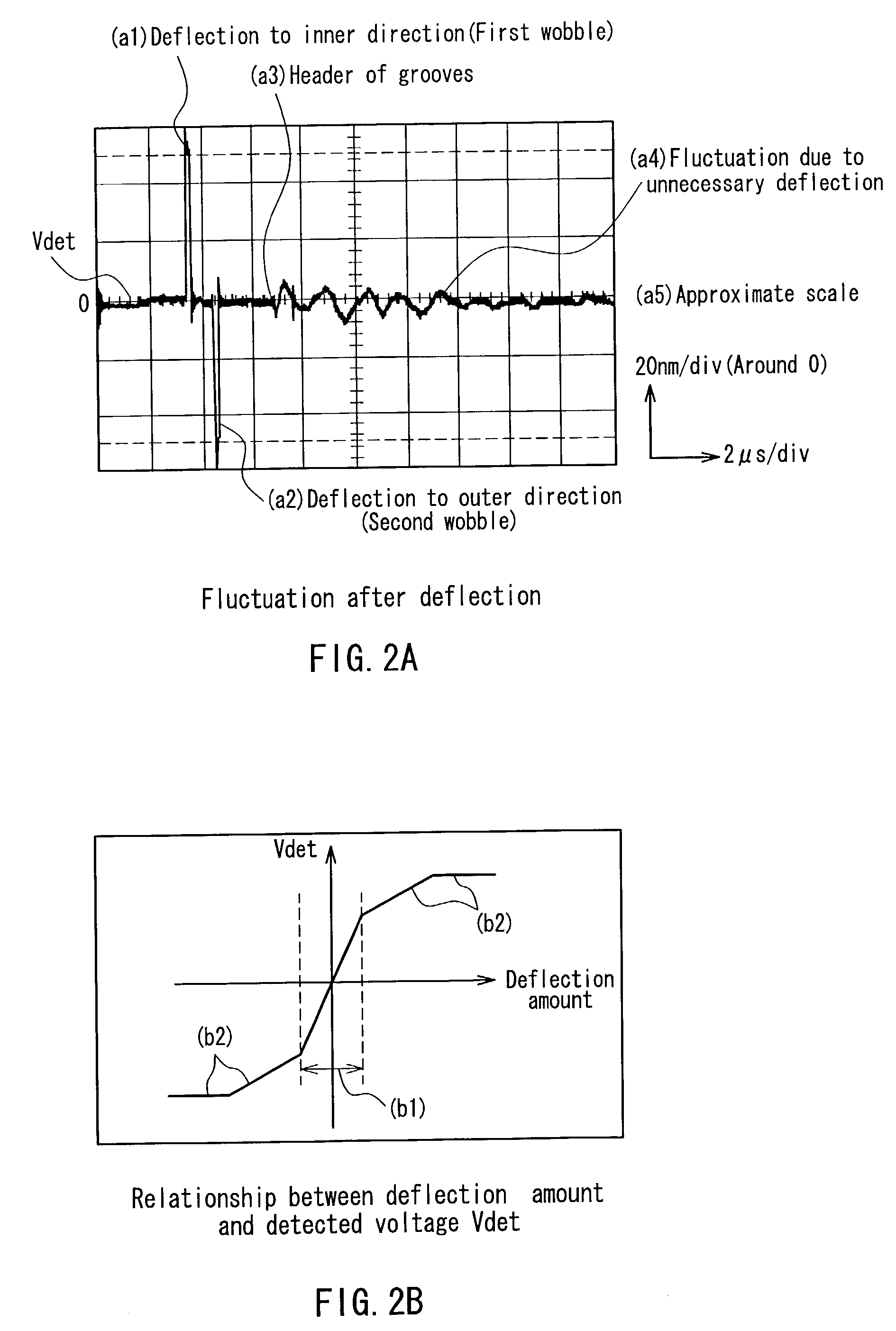
In addition, it was found that the unnecessary optical variation (variation of light intensity) that is synchronous to the deflection of the problem 1 and problem 2 is observed.
The laser beam source itself is controlled to an appropriate level by optical power servo, however, the unnecessary deflection may be caused by the following fluctuation of the EO modulator, the EO deflector, the optical components property or an optical path.

Method used


Image

  • Optical disc cutting apparatus and method for manufacturing optical disc
  • Optical disc cutting apparatus and method for manufacturing optical disc
  • Optical disc cutting apparatus and method for manufacturing optical disc

Examples


first embodiment

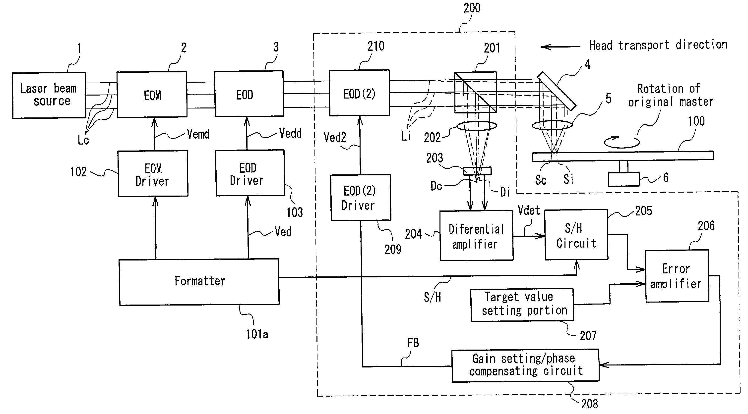
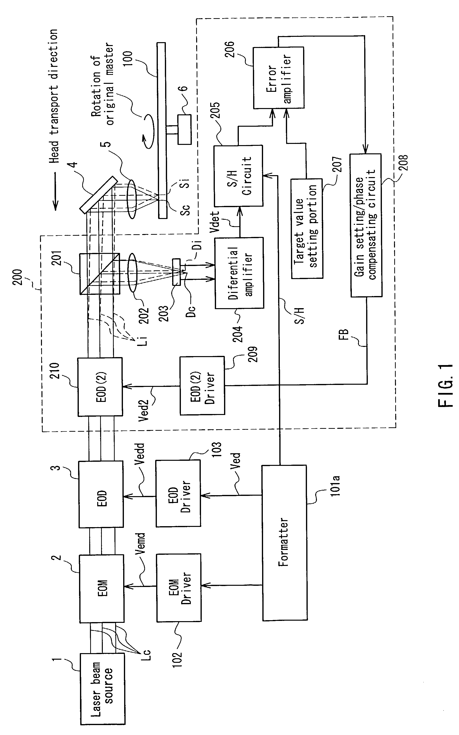
[0094]FIG. 1 is a block diagram showing an optical disc cutting apparatus of the first embodiment of the present invention. The block diagram shown in FIG. 1 shows a configuration and process of the optical disc cutting apparatus and also shows the process for manufacturing an optical disc original master in the process of manufacturing the optical disc. The same is true in the following FIGS. 4, 6 and 7.

[0095]The same components as those of FIG. 9 are given the same reference numbers and the explanation thereof is herein omitted. Herein, an EO modulator 3 is driven in a digital deflection mode.

[0096]The format of the optical disc that is subjected to cutting is assumed to be a format of sample servo system with grooves shown in FIG. 10A. This optical disc cutting apparatus additionally includes an unnecessary deflection suppressing portion, which is a servo controller, surrounded by a broken line 200 that suppresses an unnecessary deflection amount in the radial direction of an ori...

second embodiment

[0117]The following is an explanation of the second embodiment. As mentioned above, although the servo means in the first embodiment is sufficient for practical use, the fluctuation after the step deflection explained in the problem 1 (hereinafter, referred to as the deflection fluctuation) cannot be suppressed to a substantially negligible level. In this embodiment, an optical disc cutting apparatus includes a cancel controller for canceling the deflection fluctuation by using feedforwarding. More specifically, this embodiment is an example in which the cancel means is added to the example of the first embodiment. Of course, depending on the requirement of the format of an optical disc, an optical disc cutting apparatus may be sufficient in which only the cancel controller is mounted by omitting the servo controller of the first embodiment. The same is true in the following third embodiment.

[0118]FIG. 4 is a block diagram showing an optical disc cutting apparatus according to this ...

third embodiment

[0132]The following is an explanation of the third embodiment. This embodiment is an improvement of the second embodiment. Two EO deflectors are used in the second embodiment, but one EO deflector is used in this embodiment. In this embodiment, it is not necessary to add an expensive EO deflector. FIG. 6 is a block diagram showing an optical disc cutting apparatus of the third embodiment. The same components as in the second embodiment are given the same reference numbers and the explanation thereof is omitted. The optical disc cutting apparatus of this embodiment which is different from the EO deflector of the second embodiment are a formatter 101b, a timing control portion 305a, and an addition of amplifier 308a for sharing the EO deflector shown by 400 and an EOD driver 103a. For sharing, the second EOD driver 209 and the second EO deflector 210 are eliminated.

[0133]The control signal Ved 2 for controlling EOD driver from the formatter 101b is an analog signal before amplificatio...


PUM

PropertyMeasurementUnit
wavelengthaaaaaaaaaa
voltageaaaaaaaaaa
wavelengthaaaaaaaaaa

Abstract

An optical disc cutting apparatus capable of suppressing an unnecessary deflection component and unnecessary light intensity variation component and manufacturing a optical disc suitable for a high definition, high precision and high density optical disc. The optical disc cutting apparatus includes a light beam controller including at least one of an optical modulator for controlling the light intensity of light beam emitted from a laser beam source and an optical deflector for controlling the deflection amount of the light beam in the radial direction on an optical disc original master, a deflection error detector for detecting a deflection error in the radial direction included in the light beams controlled by the light beam controller, a second optical deflector, which is disposed between the light beam controller and the deflection error detector, for deflecting the light beams in the radial direction, and a feedback controller for feeding back a feedback signal using the deflection error in the radial direction to the second optical deflector.

Description

BACKGROUND OF THE INVENTION[0001]1. Field of the Invention[0002]The present invention relates to an optical disc cutting apparatus and a method for manufacturing an optical disc.[0003]2. Description of the Related Art[0004]Recently, optical discs increasingly have been applied to an AV (audio visual) field. For example, in DVD (Digital Versatile Disc) mainly for movie contents, write-once type and re-writable type formats such as DVD-R, DVD-RAM, DVD-RW, have been developed and are becoming widespread as a next generation recording apparatus of VTR.[0005]In the future, with the availability of BS digital broadcasts or broadband communication, large capacity optical disc formats capable of recording higher quality compressed pictures and optical disc formats having a small and portable size even with the same capacity and exhibiting high affinity to the network are expected.[0006]In order to realize a high-density optical disc as mentioned above, it is indispensable to develop materia...

Claims


Application Information

Patent Timeline
Patent Type & Authority Patents(United States)
IPC IPC(8): G11B11/03G11B7/007G11B7/09G11B7/125G11B7/26
CPCG11B7/261G11B7/128G11B7/00718G11B7/0938
Inventor ISHIBASHI, KENZONISHIKIORI, KEIJIHINO, YASUMORIBIRUKAWA, MASAHIRO
Owner PANASONIC CORP
Learn More