Lighting device of a motor vehicle

a motor vehicle and light technology, applied in the direction of protective devices for lighting, lighting and heating apparatus, lighting heating/cooling arrangements, etc., can solve the problems of increased space requirements, extra effort and expense in the production and assembly of light modules, etc., and achieve the effect of improving the heat emission of the carrier modul

Active Publication Date: 2011-06-23
AUTOMOTIVE LIGHTING REUTLINGEN GMBH
View PDF6 Cites 6 Cited by
  • Summary
  • Abstract
  • Description
  • Claims
  • Application Information

AI Technical Summary

Benefits of technology

[0014]Another advantage of the light module for a lighting device of a motor vehicle of the invention is that the safeguard required in the related art in the controller and semiconductor light source—e.g., in the form of a short-circuit protection—can be saved.
[0015]Another advantage of the light module for a lighting device of a motor vehicle of the invention is that it is possible to remove the light module or a part of it (including the carrier module), control module, and semiconductor light sources as a unit from the lighting device and exchange it for another “LED” light module.
[0016]Another advantage of the light module for a lighting device of a motor vehicle of the invention is that it can be designed in a compact manner.
[0017]Another advantage of the light module for a lighting device of a motor vehicle of the invention is that heat emission by the carrier module is improved.
[0018]Another advantage of the light module for a lighting device of a motor vehicle of the invention is that the electrical connection between the semiconductor light sources and circuit of the control module can be designed to be rigid since the semiconductor light sources cannot be moved relative to the control module.
[0019]Another advantage of the light module for a lighting device of a motor vehicle of the invention is that the entire light module with the semiconductor light sources and control module can be moved as one unit.

Problems solved by technology

Since the control of the semiconductor light sources normally takes place via a pulse-width modulation and the steep edges of the pulse-width modulated-control signal can cause electromagnetic disturbances, the connection cable must be screened between the controller and LEDs.
The spatial separation of semiconductor light sources, on the one hand, and the control module, on the other hand, in the case of the known light modules, hence, leads to increased space requirements as well as extra effort and expenses in the production and assembly of the light module.

Method used


Image

  • Lighting device of a motor vehicle
  • Lighting device of a motor vehicle
  • Lighting device of a motor vehicle

Examples


Embodiment Construction

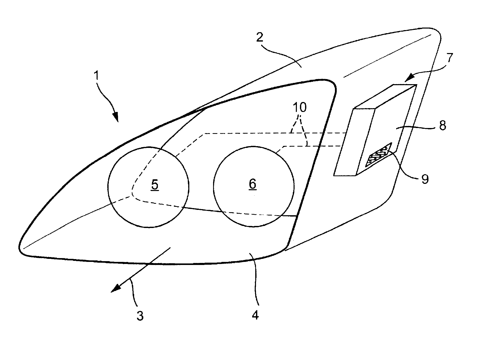
[0023]In FIG. 1, an embodiment of known lighting device for a motor vehicle in its entirety is generally indicated at 1. The lighting device 1 is designed as a motor-vehicle headlight. Of course, the lighting device 1 can also be designed as a light—for example, for arrangement on the rear or a side of the motor vehicle. The headlight 1 includes a housing 2, which can be made of plastic. The housing 2 includes a light-emission opening in one light-emission direction 3 of the headlight 1 that is sealed by a transparent sealing plug 4. The sealing plug 4 can be designed without an optically active profile (e.g., prisms) as a so-called “clear plug.” As an alternative, the sealing plug 4 can also be provided (at least in regions) with optically active elements that effect a dispersion of the penetrating light (in particular, in a horizontal direction) and, with this, improve or facilitate the fulfillment of legal requirements for light distribution. The sealing plug 4 can be made of col...


PUM


Abstract

A light module (5, 6) for a lighting device (1) of a motor vehicle includes at least one semiconductor light source (17), a control module (7) connected to the light source (17) and including an electric circuit and a connection element (9) adapted to be connected to a higher-level controller and/or power supply of the motor vehicle, and a substantially highly thermally conductive carrier module (10) to which the light source (17) and electric circuit are arranged. A lighting device (1) of a motor vehicle includes the light module (5, 6).

Description

CROSS-REFERENCE TO RELATED APPLICATION[0001]This application claims priority to and benefit of the filing date of German Patent Application 10 2009 060 790.0 entitled “Light Module for a Lighting Device of a Motor Vehicle as Well as the Lighting Device of a Motor Vehicle with Such a Light Module” and filed on Dec. 22, 2009.BACKGROUND OF INVENTION[0002]1. Field of Invention[0003]The invention relates, generally, to a lighting device of a motor vehicle and, more specifically, to a light module employed with such a lighting device.[0004]2. Description of Related Art[0005]Lighting devices for motor vehicles that include semiconductor light sources—for example, in the form of light-emitting diodes (LEDs)—are known from the related art in various forms. Such lighting devices can be designed as a random motor-vehicle light—in particular, for arrangement on the rear or side of a motor vehicle.[0006]However, the lighting devices can likewise be designed as “LED” headlights. In this connectio...

Claims


Application Information

Patent Timeline
Patent Type & Authority Applications(United States)
IPC IPC(8): F21S8/10F21W107/10H05B44/00
CPCB60Q1/0094F21S48/1109Y02B20/341H05B33/0803F21S48/328F21S48/115F21S41/192F21S45/47F21S45/48F21S41/151F21S45/435H05B45/30
Inventor SCHNERR, MICHAELBLUM, DIRK
Owner AUTOMOTIVE LIGHTING REUTLINGEN GMBH
Why Eureka
Try Eureka