Imprint apparatus, imprint method, and article manufacturing method
- Summary
- Abstract
- Description
- Claims
- Application Information
AI Technical Summary
Benefits of technology
Problems solved by technology
Method used
Image
Examples
first embodiment
[0021]Embodiments of the present invention will now be described with reference to the attached drawings. The present invention is not only useful in forming fine nanoscale patterns, but is applicable to formation of patterns larger than nanoscale patterns.
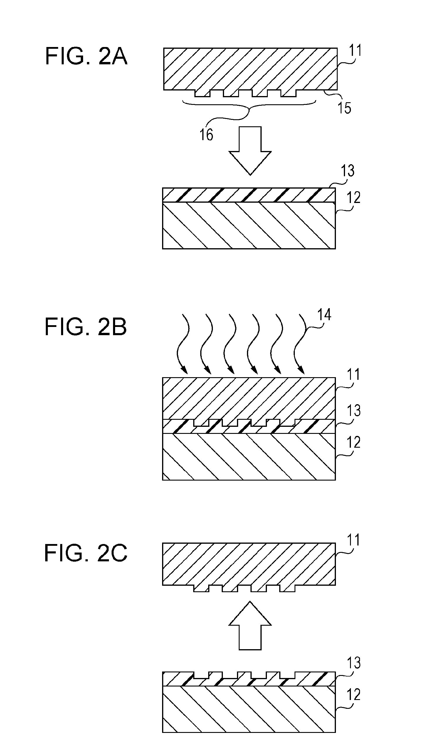
[0022]First, a flow of pattern transfer based on a photo-imprint method will be described with reference to FIG. 2A to FIG. 2C. In the step of FIG. 2A, a mold 11 is pressed against an imprint resin (hereinafter referred to as a resin) 13 dispensed to a substrate 12, such as a silicon wafer or a glass wafer. The resin most often used today is a monomer resin. The mold 11 is made of UV transmitting material, such as quartz. A lower surface (patterned surface) 15 of the mold 11 has a pattern 16 for molding. When the resin 13 and the mold 11 are pressed together, the resin 13 is fluidized and filled into the concave portions of the pattern 16. The resin 13 is thus molded into a certain shape.
[0023]In the step of FIG. 2B, while the res...
second embodiment
[0049]An aspect of an imprint apparatus and method according to a second embodiment of the present invention will now be described with reference to FIG. 4A to FIG. 4C. The first embodiment allows switching between two sets (ranges) of ports, while the second embodiment allows switching between three sets of ports.
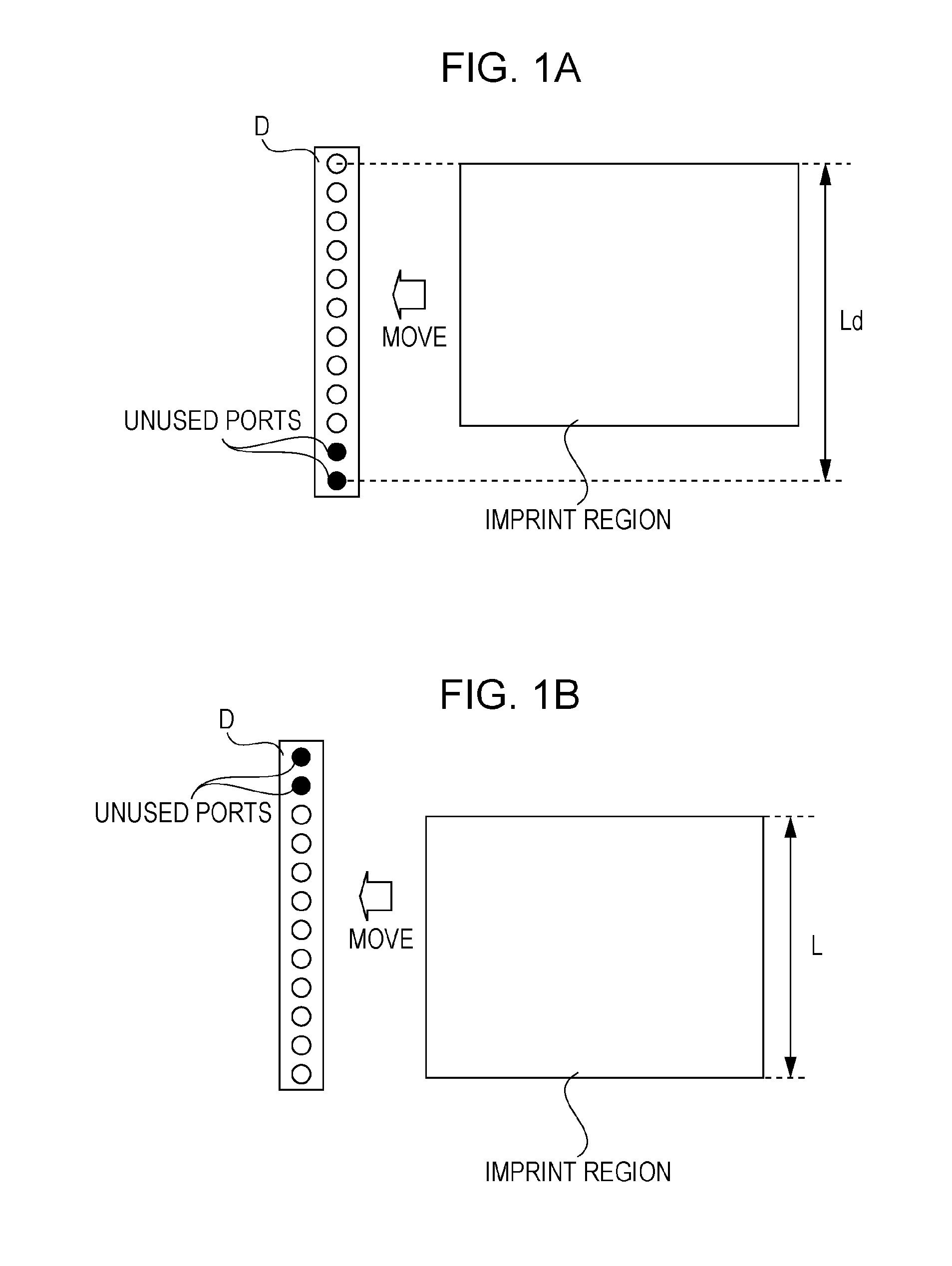
[0050]Referring to FIG. 4A to FIG. 4C, the vertical side of the imprint region in the drawing is shorter than half the length of the discharge section D in the longitudinal direction. In this case, with the configuration of the first embodiment (see FIG. 1A and FIG. 1B), some of the ports are left unused. Accordingly, an example of switching between three sets of ports will be described here. For dispensing of resin to an imprint region, ports in the upper part of the discharge section D are used in FIG. 4A, ports in the center of the discharge section D are used in FIG. 4B, and ports in the lower part of the discharge section D are used in FIG. 4C.
[0051]As in the case of ...
PUM
| Property | Measurement | Unit |
|---|---|---|
| Time | aaaaa | aaaaa |
| Size | aaaaa | aaaaa |
Abstract
Description
Claims
Application Information
 - R&D
- Intellectual Property
- Life Sciences
- Materials
- Tech Scout
- Unparalleled Data Quality
- Higher Quality Content
- 60% Fewer Hallucinations
Browse by: Latest US Patents, China's latest patents, Technical Efficacy Thesaurus, Application Domain, Technology Topic, Popular Technical Reports.
© 2025 PatSnap. All rights reserved.Legal|Privacy policy|Modern Slavery Act Transparency Statement|Sitemap|About US| Contact US: help@patsnap.com


