Anterior Lumbar Interbody

a technology of lumbar spine and interbody, which is applied in the field of medical devices for the spine, can solve the problems of most costly health problems for society, back pain and pathology of the spine, and great suffering for victims

Inactive Publication Date: 2011-06-23
CUSTOM SPINE INC
View PDF5 Cites 124 Cited by
  • Summary
  • Abstract
  • Description
  • Claims
  • Application Information

AI Technical Summary

Problems solved by technology

One of the most costly health problems to society involves back pain and pathology of the spine, which can be caused by several factors.
These problems can affect individuals of all ages and can result in great suffering to victims.
Although this procedure may result in some minor loss and flexibility in the spine, due to the relatively large number of vertebrae, the minor loss of mobility is typically acceptable.
While m

Method used


Image

  • Anterior Lumbar Interbody
  • Anterior Lumbar Interbody
  • Anterior Lumbar Interbody

Examples


first embodiment

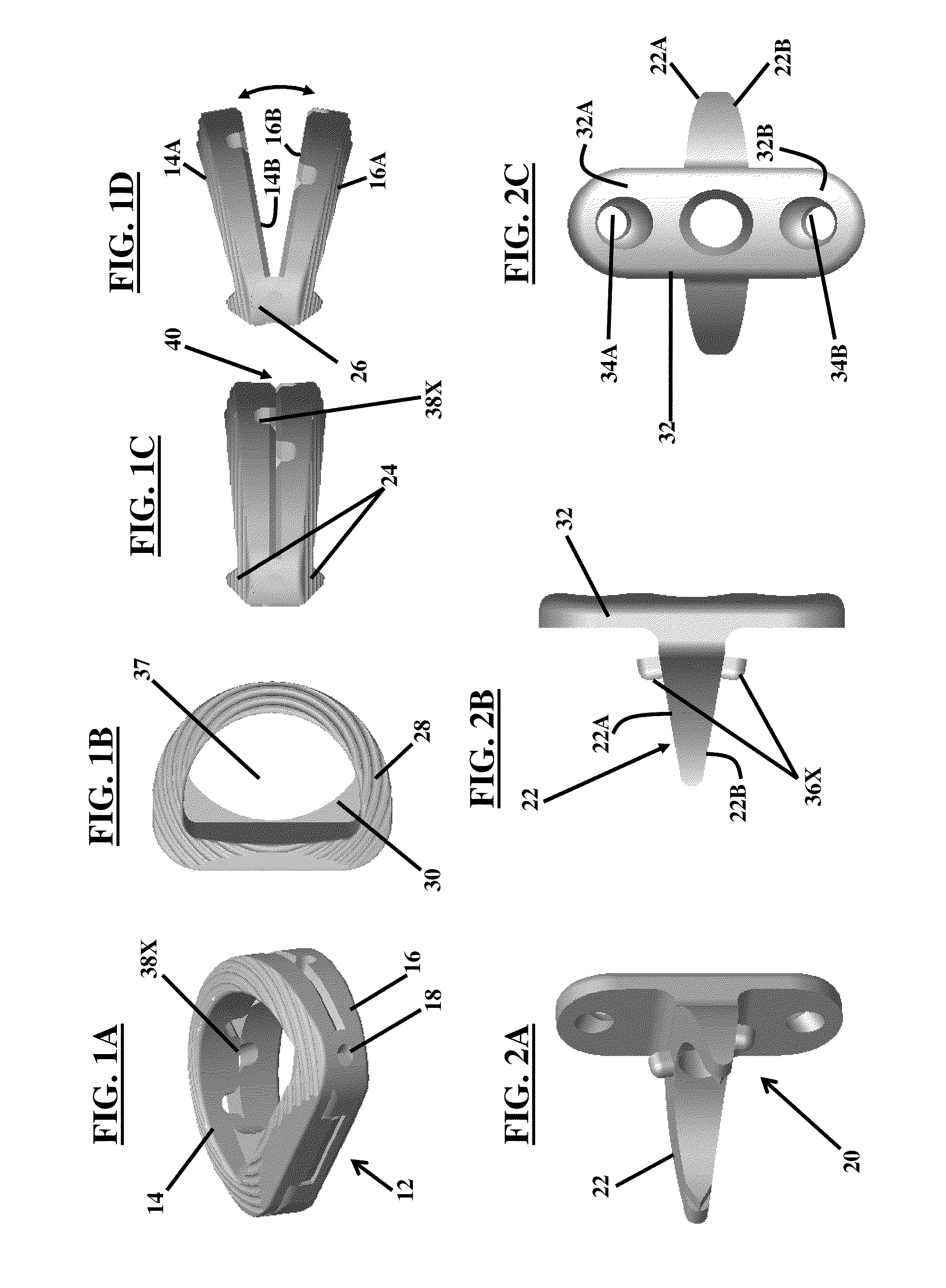
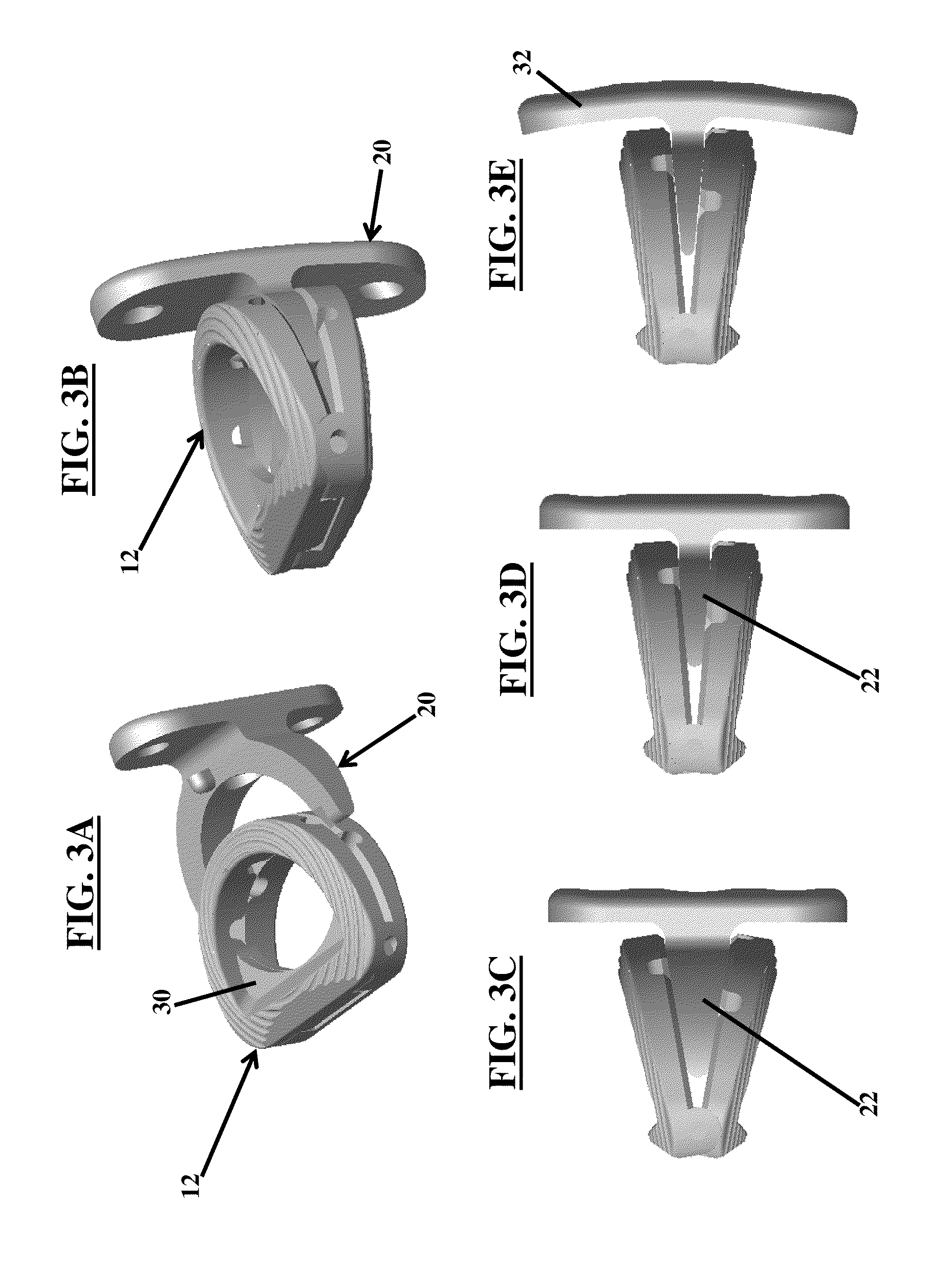
[0048]A first embodiment herein, illustrated in FIGS. 1A through 4B, provides an expandable intervertebral fusion implant system 10 for insertion between two vertebrae bodies 1000, as best illustrated in FIGS. 4A and 4B. Referring to FIGS. 1A through 3E, the system 10 includes an anterior lumbar interbody component 12 having an upper component 14 and a lower component 16 each having an inner and outer surface 14A, 14B, 16A, 16B. The upper and lower components 14, 16 are pivotally connected through a hinge 18 allowing opening and closing for positioning as described herein. A distracting component 20 includes a wedge 22 having a superior 22A and inferior surface 22B. The wedge 22 is configured to insert between the upper 14 and lower 16 components of the anterior lumbar interbody component 12 based on the “open and close” movement allowed by the hinge 18. This positioning and movement allows the outer surfaces 14A, 16A of the upper 14 and lower 16 components to contact endplates 1002...

second embodiment

[0053]Referring to FIGS. 5A through 5C, a second embodiment herein is illustrated comprising an expandable intervertebral fusion implant apparatus 110 for insertion between two vertebrae bodies (e.g., vertebrae 1000 of FIGS. 4A and 4B). The apparatus 110 includes an anterior lumbar interbody component 112 comprising an upper component 114 and a lower component 116, each having an inner surface 114B, 116B and outer surface 114A, 116A; the upper 114 and lower 116 components are pivotally connected through a hinge 118. A distracting component 120 includes a wedge 122 having a superior 122A and inferior 122B surface. The wedge 122 is configured to insert between the upper 114 and lower 116 components of the anterior lumbar interbody component 112. A second end 140 of each of the upper 114 and the lower 116 component includes an angled bone screw guide 150, 152.

[0054]The distracting component 120 further includes a securing component 132 continuous with the wedge 122 via an extension bar...

third embodiment

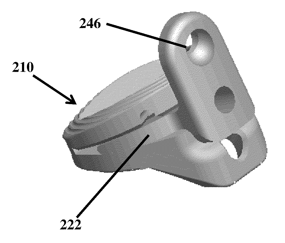
[0057]In FIGS. 6A through 6E, with reference to FIGS. 1A through 5C, a third embodiment herein is illustrated comprising an expandable intervertebral fusion implant apparatus 210 for insertion between two vertebrae bodies (e.g., vertebrae 1000 of FIGS. 4A and 4B). The apparatus 210 includes an anterior lumbar interbody component 212 comprising an upper component 214 and a lower component 216 each having an inner and outer surface 214A, 214B, 216A, 216B, and pivotally connected through a hinge 218 located at a first end 226 of the interbody component 212. A second end 240 of the interbody component 212 includes an extended portion 216E connected to the lower component 216, wherein the extended portion 216E comprises an angled bone screw guide 250E.

[0058]The outer surfaces 214A, 216A of the upper component 214 and the lower component 216 each include a vertebrae position device 224 at a first end 226 proximal to the hinge 218. The vertebrae position device 224 allows for an improved f...


PUM


Abstract

A system having an expandable intervertebral fusion implant assembly for insertion between two vertebrae bodies. The system includes an anterior lumbar interbody component having an upper component and a lower component, each having an inner and outer surface, pivotally connected through a hinge. A distracting component includes a wedge having a superior and inferior surface that inserts between the upper and lower components of the anterior lumbar interbody component. The outer surface of the upper and the lower component contact endplates of two adjacent vertebral bodies.

Description

BACKGROUND[0001]1. Technical Field[0002]The embodiments herein generally relate to medical devices, and, more particularly, to medical devices for the spine.[0003]2. Description of the Related Art[0004]One of the most costly health problems to society involves back pain and pathology of the spine, which can be caused by several factors. These problems can affect individuals of all ages and can result in great suffering to victims.[0005]Upon identification of these abnormalities, surgery may be required to correct the problem. One method of correction is spinal fusion, wherein vertebrae are fixed together to prevent movement and maintain a space originally occupied by an intervertebral disk. During a spinal fusion, a prosthetic implant or spinal implant is inserted into the intervertebral space. Although this procedure may result in some minor loss and flexibility in the spine, due to the relatively large number of vertebrae, the minor loss of mobility is typically acceptable.[0006]M...

Claims


Application Information

Patent Timeline
IPC IPC(8): A61F2/44
CPCA61F2/4465A61F2002/4475A61F2002/30401A61F2002/30515A61F2002/30538A61F2002/30578A61F2002/30579A61F2002/30599A61F2002/30604A61F2002/30607A61F2002/30611A61F2002/30616A61F2002/30629A61F2002/30632A61F2002/30736A61F2002/30825A61F2002/30827A61F2002/30879A61F2002/30904A61F2002/30331A61F2002/30624A61F2002/30593
Inventor ABDELGANY, MAHMOUD F.SICHLER, KEVIN
Owner CUSTOM SPINE INC
Why Eureka
Try Eureka