
Sensor-Based Implement Motion Interlock System

Inactive Publication Date: 2011-06-23
AGCO CORP
View PDF24 Cites 28 Cited by
  • Summary
  • Abstract
  • Description
  • Claims
  • Application Information

AI Technical Summary

Benefits of technology

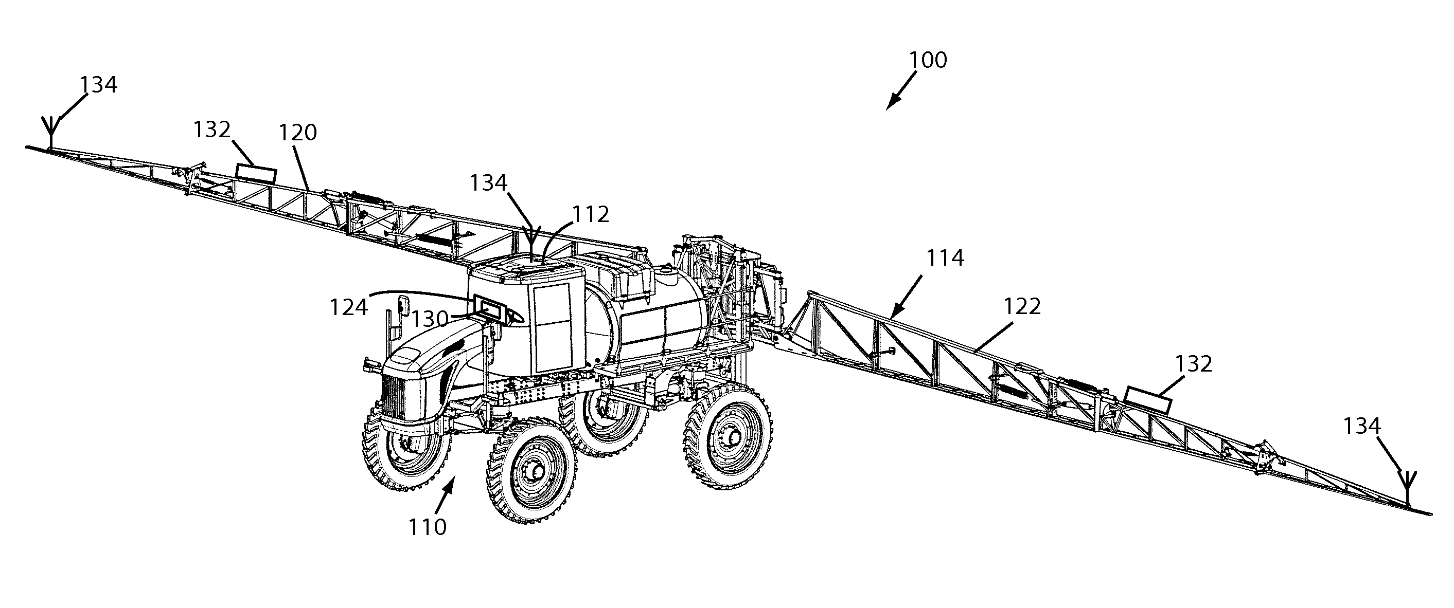
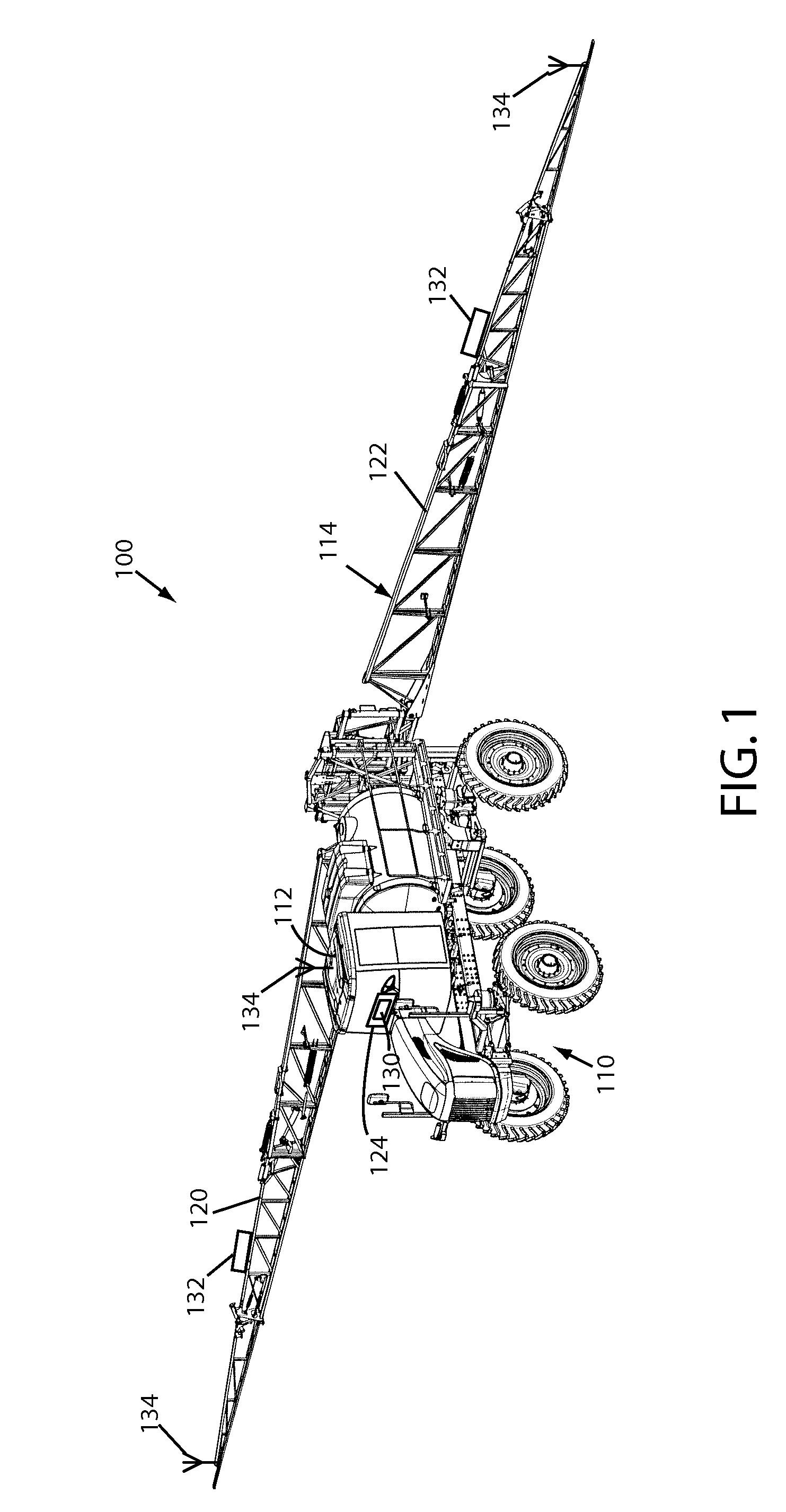
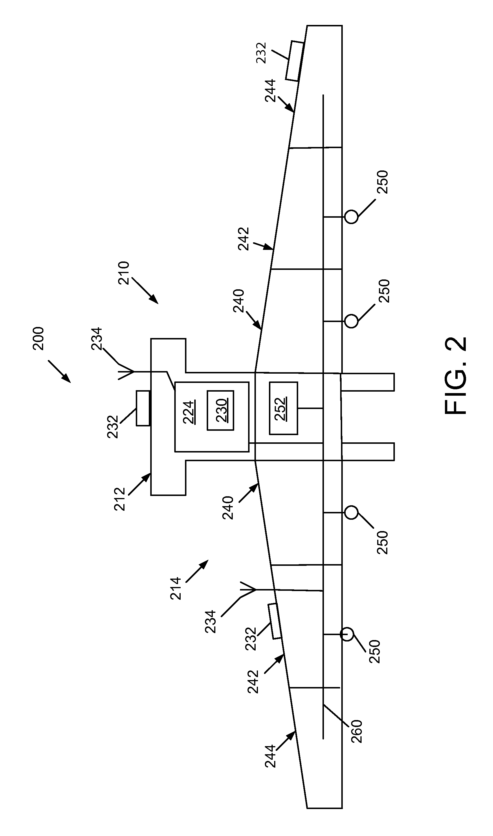
[0006]The present invention provides systems and methods for controlling implement movement in the presence of an obstacle, such as by way of example and not limitation, an electric power line. An example system can include at least one sensor adapted to detect the presence of an object, such as an electrical transmission line, an alarm module configured to receive input from the at least one sensor and provide an alarm status; and a controller configured to check the alarm status at the alarm module and prevent implement motion when the alarm status indicates that the object is present. An example system can further include an operator override switch by which an o

Problems solved by technology

However, manually controlled boom operations are subject to human factor errors.
Operators may not have an unobstructed view of the field and / or air space surrounding them.
In addition, operators may have delayed reaction times that prevent them from manipulating the booms quickly enough to avoid obstacles.
Furthermore, operators of agricultural vehicles are often inexperienced and have little training in regards to the potential hazards of operating such equipment.
While useful for detecting masses such as the ground or large obstacles, ultrasonic sensors may not be as effective in detecting targets with small cross-sections, or obstacles in the air space above the vehicle.
With implement spans of 90′ or more, implement wings may inadvertently cross power lines during an elevation procedure.
Contact with power lines can be lethal.
In addition to posing a hazard to agricultural vehicle operators, power lines can also damage the agricultural machinery itself.
Furthermore, fellow workers or bystanders can be electrocuted or shocked by touching charged equipment or downed power lines, or while attempting to assist someone who has been electrocuted.

Method used


Image

  • Sensor-Based Implement Motion Interlock System
  • Sensor-Based Implement Motion Interlock System
  • Sensor-Based Implement Motion Interlock System

Examples


Embodiment Construction

[0013]As required, example embodiments of the present invention are disclosed herein. The various embodiments are meant to be non-limiting examples of various ways of implementing the invention and it will be understood that the invention may be embodied in alternative forms. The present invention will be described more fully hereinafter with reference to the accompanying drawings in which like numerals represent like elements throughout the several figures, and in which example embodiments are shown. The figures are not necessarily to scale and some features may be exaggerated or minimized to show details of particular elements, while related elements may have been eliminated to prevent obscuring novel aspects. The specific structural and functional details disclosed herein should not be interpreted as limiting, but merely as a basis for the claims and as a representative basis for teaching one skilled in the art to variously employ the present invention. The example embodiments ar...


PUM


Abstract

In an example embodiment, a sensor based implement motion interlock comprises, a sensor for detecting an obstacle near the implement and a controller configured to stop movement of the implement when the obstacle is detected. An override switch may be provided to allow an operator to move the implement in a safe mode after the object is detected. The override switch may be positioned to ensure that the operator is cognizant of the obstacle during movement of the implement. A normal mode of operation may be resumed when the object is no longer in proximity and / or an operation of the implement is complete.

Description

TECHNICAL FIELD[0001]The present invention relates generally to agricultural vehicles, and more particularly to sensor-based systems that control movement of an attached implement.BACKGROUND OF INVENTION[0002]Global competition compels farmers to modify cultivation practices by incorporating more cost-effective farming techniques and acquiring more efficient machinery. In doing so, farmers have increasingly turned to larger machinery and more sophisticated technology that automates and optimizes the operation of agricultural vehicles and equipment. Liquid and dry air boom type crop applicators have been used to apply a variety of crop inputs, such as fertilizer, nutrients, seed and crop protectants, herbicides, insecticides, and the like in site specific farming applications. Agricultural vehicles can apply crop inputs based on algorithms that incorporate geographical information as well as soil data, crop data, and the like to determine the amount and placement of crop inputs neede...

Claims


Application Information

Patent Timeline
IPC IPC(8): G06F7/00
CPCA01M7/0089A01M7/0075
Inventor PETERSON, JOHN
Owner AGCO CORP
Learn More