
Exhaust liner cable fastener

Active Publication Date: 2018-11-15
RAYTHEON TECH CORP
View PDF6 Cites 0 Cited by
  • Summary
  • Abstract
  • Description
  • Claims
  • Application Information

AI Technical Summary

Benefits of technology

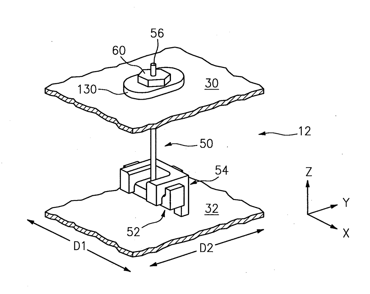
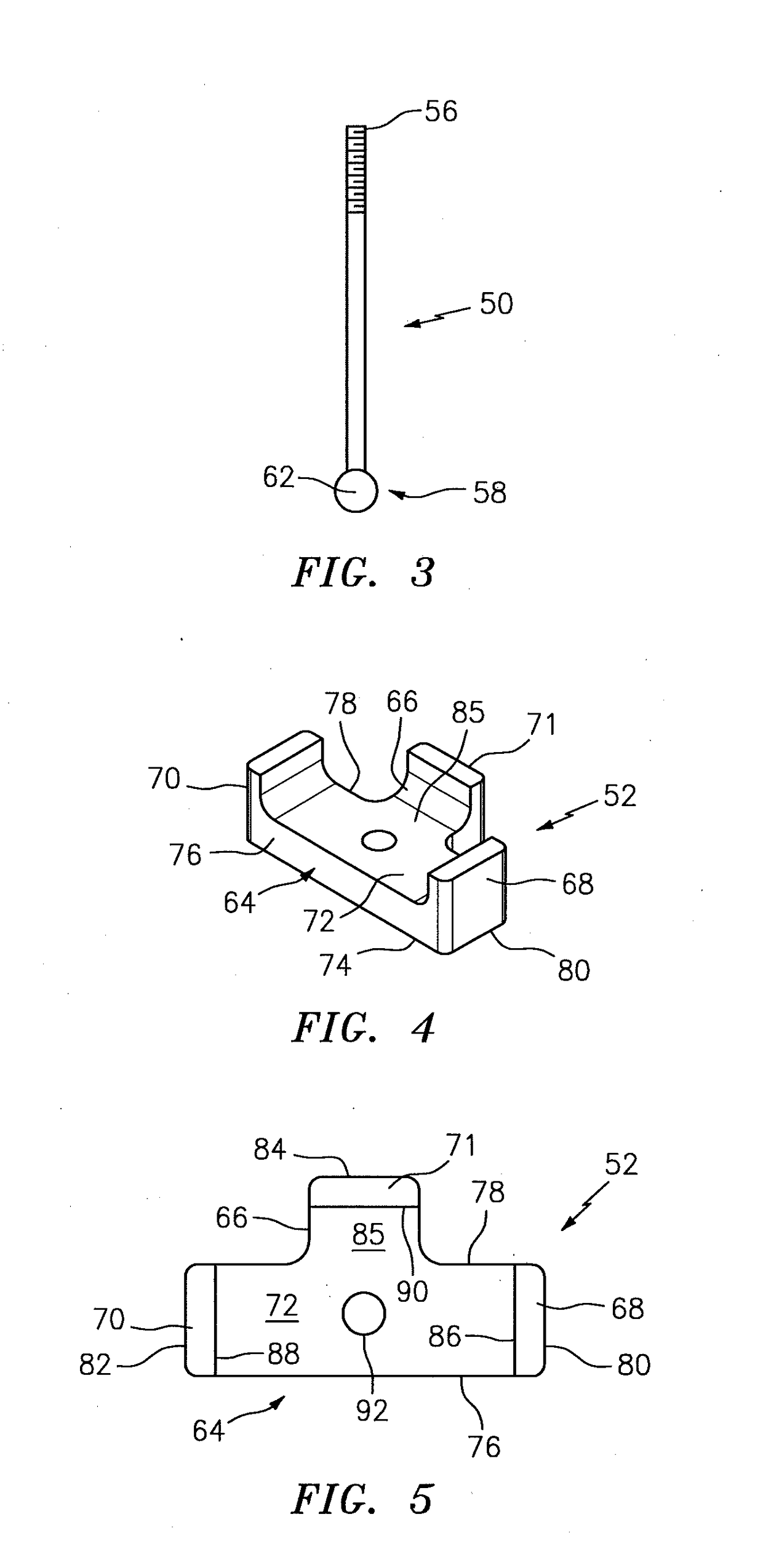
The present disclosure provides a hanger for mounting an exhaust liner to an exhaust duct. The hanger includes at least one cable, a cable flange, and a J-shaped flange. The at least one cable extends lengthwise between a first end and a second end. The cable flange has at least one cable aperture configured to receive a portion of the cable. The J-shaped flange is configured for attachment to the exhaust liner. The liner flange and cable flange are configured to mate with one another in two directions that are substantially orthogonal to each other, preventing substantial relative motion between them. This design ensures secure mounting of the exhaust liner to the exhaust duct and reduces the risk of damage to the exhaust liner during installation.

Problems solved by technology

Exhaust gases, however, may reach much higher temperatures, particularly if thrust augmentation is utilized.
Thus, the exhaust duct and liner are subjected to different pressure and temperature gradients, which results in differing deflections and expansions of each body.
The differing pressures, temperatures and functional requirements of the exhaust duct, however, produce three-dimensional forces between the duct and liner, which tend to shift the liner out of alignment.
Some of these designs, however, require careful insertion of support members through holes in either the exhaust duct or liner.

Method used


Image

  • Exhaust liner cable fastener
  • Exhaust liner cable fastener
  • Exhaust liner cable fastener

Examples


Embodiment Construction

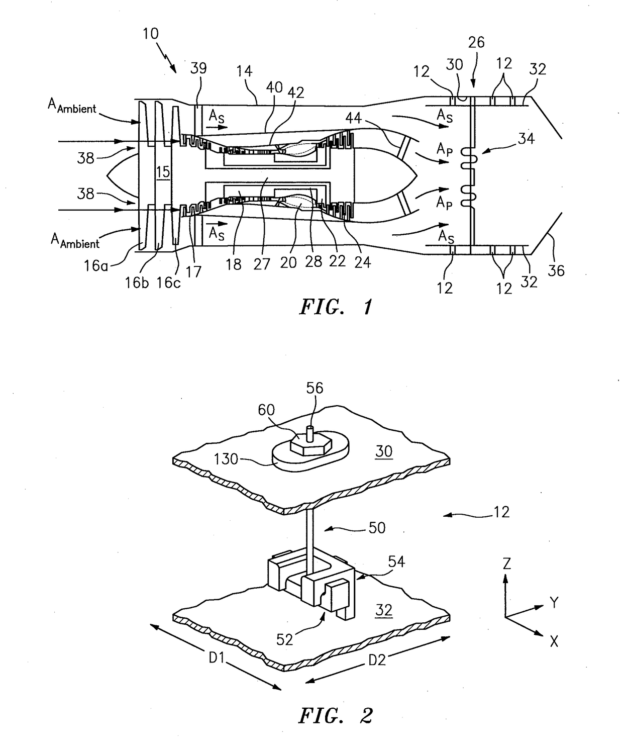
[0034]FIG. 1 shows a schematic diagram of dual-spool, low-bypass ratio turbofan engine 10, in which hangers 12 of the present invention can be used. Although, in other embodiments, the present invention is applicable to other types of gas turbine engines such as high-bypass ratio turbofans including turbofans using fan drive gear systems. Turbofan engine 10 also includes fan duct 14, drive fan 15 (including stages 16a-16c), low pressure compressor 17, high pressure compressor 18, combustor 20, high pressure turbine 22, low pressure turbine 24 and exhaust system 26. Drive fan 15 and low pressure compressor 17 are driven by low pressure turbine 24 with shaft 27. High pressure compressor 18 is driven by high pressure turbine 22 with shaft 28. High pressure compressor 18, combustor 20, high pressure turbine 22 and shaft 28 comprise the core of turbofan engine 10, which produces the high energy air stream that is ultimately used to drive low pressure turbine 24 and provide high pressure ...


PUM


Abstract

A hanger for mounting an exhaust liner to an exhaust duct is provided. The hanger includes at least one cable, a cable flange, and a J-shaped flange. The at least one cable extends lengthwise between a first end and a second end. The cable flange has at least one cable aperture configured to receive a portion of the cable. The J-shaped liner flange is configured for attachment to the exhaust liner. The liner flange and cable flange are configured to mate with one another to prevent substantial relative motion between the cable flange and the liner flange in a first direction and in a second direction. The first and second directions are substantially orthogonal to one another.

Description

[0001]This invention was made with government support under Contract No. FA8626-15-D-0015-3502 awarded by the United States Air Force. The government may have certain rights in the invention.BACKGROUND OF THE INVENTION1. Technical Field[0002]The invention relates generally to gas turbine engines and more particularly to exhaust duct liner attachment systems and methods.2. Background Information[0003]In gas turbine engines, it is necessary to protect exhaust ducts with an insulating shield in order to prevent heated core gases from damaging the exhaust ducts. Exhaust gases, however, may reach much higher temperatures, particularly if thrust augmentation is utilized. It is, therefore, necessary to line exhaust ducts with a material that is capable of withstanding the peak temperatures of the core gases and that prevents the exhaust duct from reaching its temperature limitations. In order to alleviate some of the heat from the exhaust gases imparted to the liner, cooling air is passed ...

Claims


Application Information

Patent Timeline
IPC IPC(8): F01D25/28F01D25/30F01D25/24
CPCF01D25/28F05D2260/30F01D25/243F01D25/30F02K1/822F02C7/20F05D2230/642Y02T50/60
Inventor KING, CHRISTOPHER
Owner RAYTHEON TECH CORP
Learn More