
Electrical busbar with alignment features

Active Publication Date: 2020-05-14
RIVIAN IP HLDG LLC
View PDF0 Cites 0 Cited by
  • Summary
  • Abstract
  • Description
  • Claims
  • Application Information

AI Technical Summary

Benefits of technology

The patent is about a method to connect electrical busbars together to prevent them from moving relative to each other. The method involves using boss and recess features on each busbar to connect them. This helps to keep the busbars in the correct position and orientation, which can improve the efficiency and reliability of the electrical system.

Problems solved by technology

However, the additional cost and mass (e.g., if it is a permanent part of the assembly) might not be acceptable.

Method used


Image

  • Electrical busbar with alignment features
  • Electrical busbar with alignment features
  • Electrical busbar with alignment features

Examples


Embodiment Construction

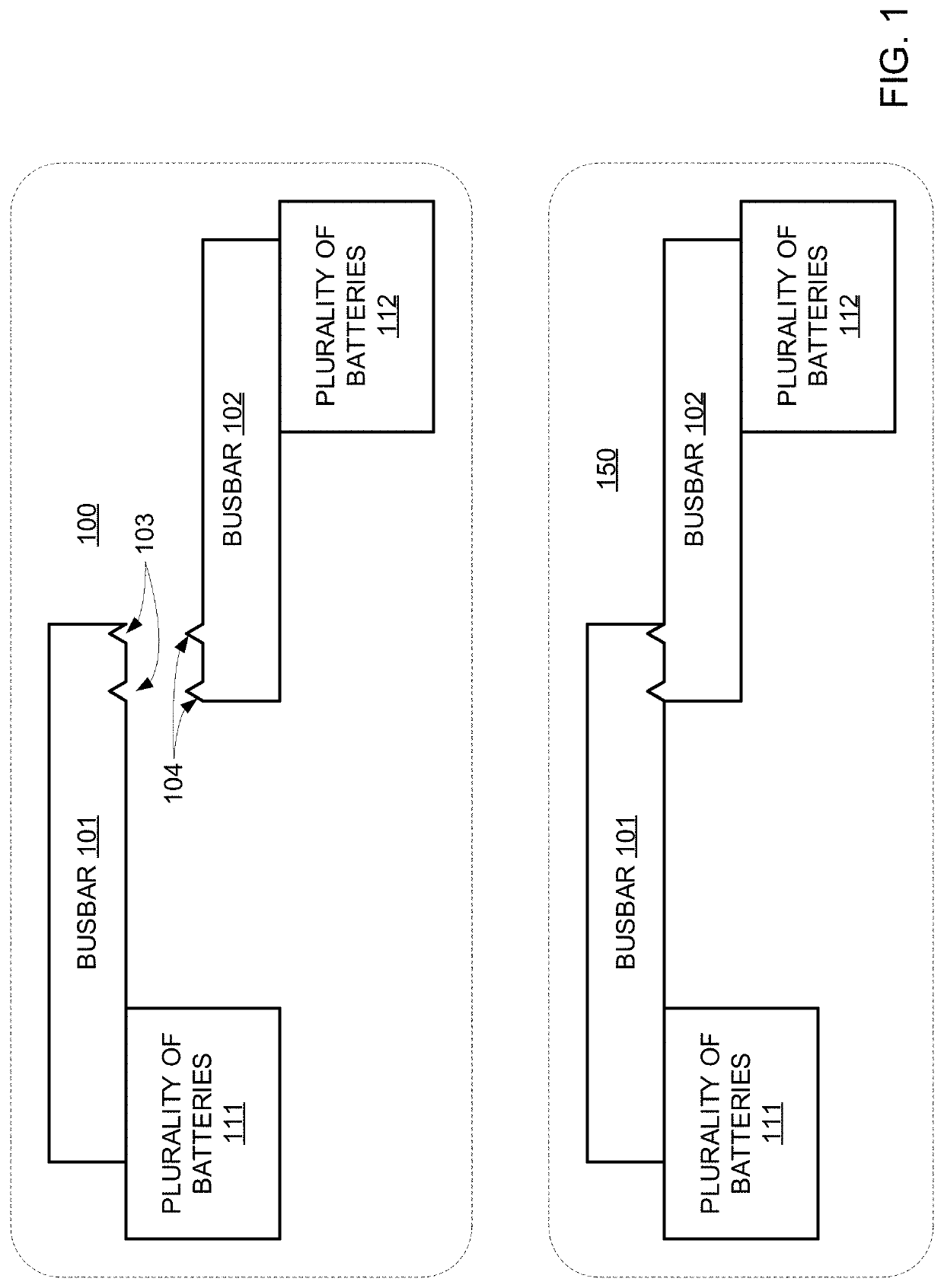
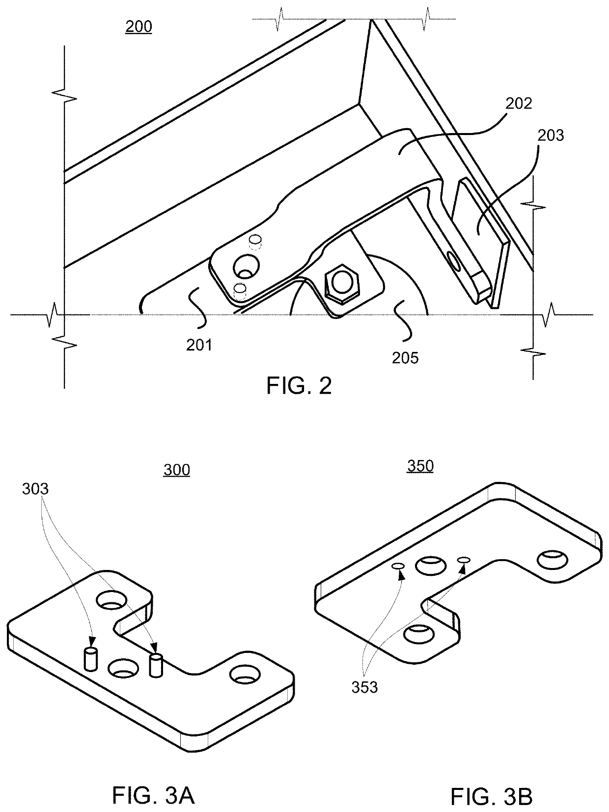
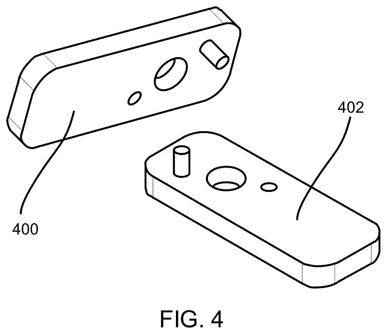
[0022]FIG. 1 shows two configurations 100 and 150 of an illustrative busbar system, in accordance with some embodiments of the present disclosure. The busbar system includes busbar 101 and busbar 102, which are each configured to engage with a respectively plurality of battery cells and provide a conduit for current. The respective pluralities of battery cells may be arranged spatially, and each of busbar 101 and busbar 102 may include features that engage with each respective battery cell to provide electrical contact. For example, busbar 101 and busbar 102 may each provide a path for current to flow in parallel from the respective plurality of battery cells. Busbar 101 and busbar 102 are electrically coupled together. For example, as illustrated, busbar 101 and busbar 102 are fastened together. Alignment features 103 of busbar 101 and alignment features 104 of busbar 102 help maintain alignment during arrangement of busbars 101 and 102, during fastening of busbars 101 and 102 toge...


PUM


Abstract

A busbar system is configured to carry current, such as, for example, in a battery system. The busbar system includes two or more busbars, that interface at respective surfaces and are aligned by one or more alignment features. The one or more alignment features may include a boss feature such as a pin or other protrusion, a recess such as a hole, slot, or other recess feature, or both a boss feature and a recess feature. Each busbar may include an alignment feature that engages with the alignment feature of the other busbar to cause, maintain, or otherwise effect alignment. Alignment of the busbars ensures relative position, prevents relative motion, or both. The busbars are engaged with each other by positioning the busbars such that their mating surfaces can engage, and then engaging alignment features of the busbars to provide alignment of the busbars relative to each other.

Description

CROSS REFERENCE TO RELATED APPLICATION[0001]This application claims the benefit of U.S. Provisional Patent Application No. 62 / 760,869 filed Nov. 13, 2018, the disclosure of which is hereby incorporated by reference herein in its entirety.[0002]The present disclosure is directed towards an electrical busbar for conducting current, and more particularly towards an electrical busbar having alignment features.INTRODUCTION[0003]Electrical busbars are used to provide a path for current among components. For example, battery systems use busbars to connect cells in parallel and / or series, couple cells to components such as switches, connectors, or fuses. Two or more busbars can be connected together to further extend the current path. It would be advantageous to provide for alignment of busbars to prevent a change in relative position, relative orientation, or both.[0004]Busbar alignment can be achieved with an assembly aid (e.g., a jig) that constrains one or both of the busbars so they ca...

Claims


Application Information

Patent Timeline
IPC IPC(8): H01M2/20H01R4/58H01R43/00H01M50/50H01M50/503
CPCH01R43/00H01M2220/20H01R4/58H01M2/206H01R25/145H01R25/142H01R13/631H01M50/503H01M50/507H01M50/509H01M50/50
Inventor O'NEIL, KYLE
Owner RIVIAN IP HLDG LLC
Learn More