
Living body optical measurement apparatus

Inactive Publication Date: 2007-08-09
HITACHI MEDICAL CORP
View PDF14 Cites 1 Cited by
  • Summary
  • Abstract
  • Description
  • Claims
  • Application Information

AI Technical Summary

Benefits of technology

[0008] In a living body optical measurement apparatus according to the present invention, a measurement chair for seating a subject is provided with a simple constitutional member which suppresses the sense of oppression being given to the subject minimum and restrains the jaw or the chest of the subject and with the constitutional member, a motion of the upper part of the subject is effectively restricted, thereby, the measurement accuracy as well as the measurement efficiency in the living body optical measurement are improved.
[0014] In the living body optical measurement apparatus according to the present invention, since the measurement chair is provided with the jaw receiving portion which receives the jaw of the subject and restricts a motion of the jaw, a motion of the head portion of the subject can be prevented with such simple constitutional member without giving the sense of oppression to the subject, thus the measurement accuracy can be improved.
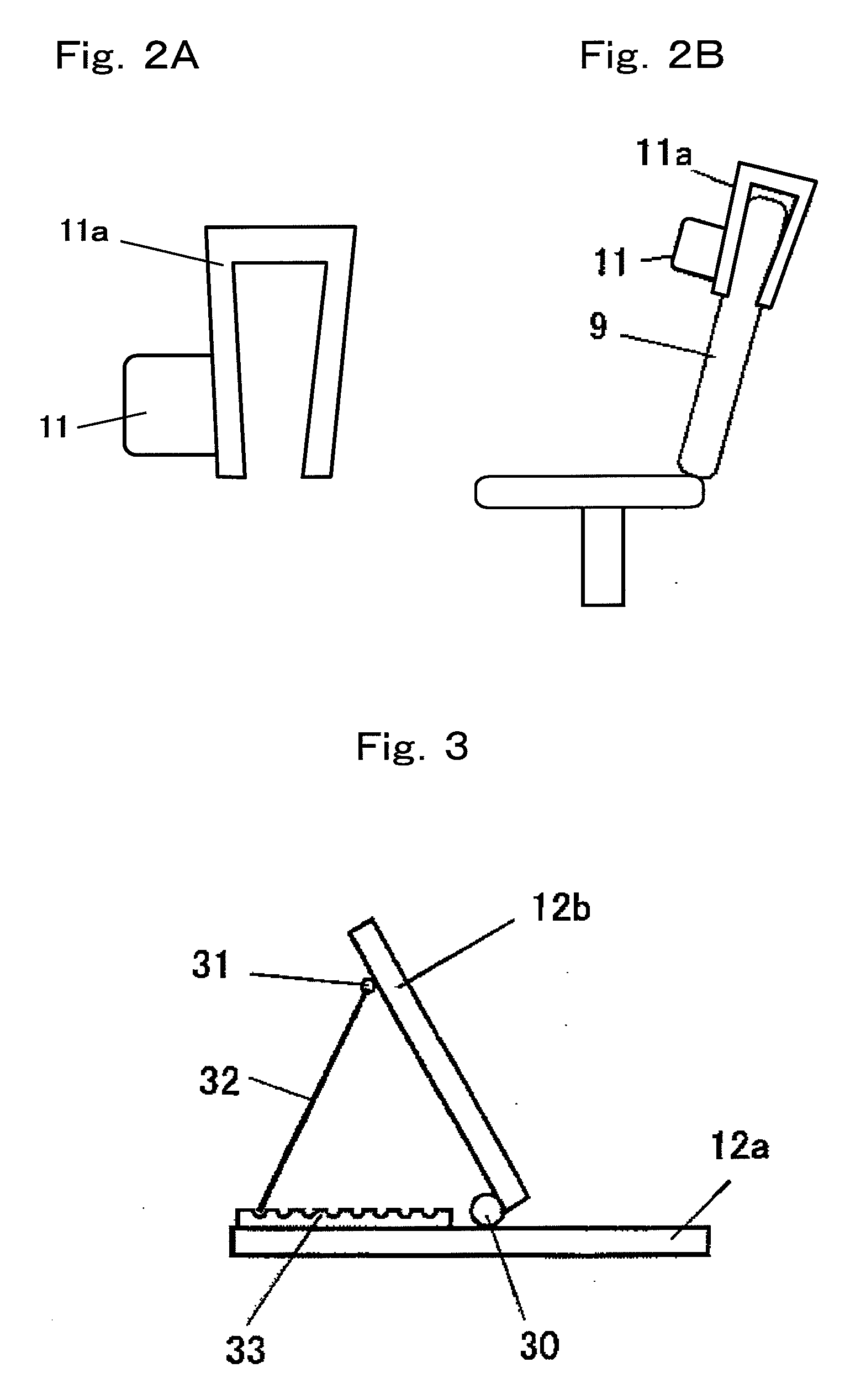
[0015] Further, since the measurement chair is provided with a desk to be arranged in front of the subject seated on the measurement chair at the time of measurement and the desk is provided with an inclined portion, for example, like a bookrack, arranged in an inclined manner with respect to the horizontal plane thereof, when the subject carries out a work such as drawing letters and pictures on the desk, a motion of the upper part can be limited and with such simple constitutional member the measurement accuracy can be enhanced.
[0016] Further, since the measurement chair is provided with the pillow portion which receives the back head portion of the subject and restricts a motion of the back head, a motion of the head portion of the subject can be prevented with such simple constitutional member without giving the sense of oppression to the subject, thus the measurement accuracy can be improved.
[0017] Further, since the measurement chair is provided with a chest member which is applied to the chest of the subject and restricts a motion of upper part of the subject, a motion of the upper part of the subject can be prevented with such simple constitutional member without giving the sense of oppression to the subject, thus the measurement accuracy can be improved.
[0018] Further, since the measurement chair is provided with a light shielding hood for covering around the head portion of the subject, influences due to external light from the circumference can be removed with such simple constitutional member, thus, the measurement accuracy can be improved.

Problems solved by technology

There was a problem that during living body optical measurement, when a subject moves (body motion), such as an attachment position, angle or contact pressure of an optical fiber probe changes and a condition of optical passages change, thereby, the measurement accuracy reduces.
For this reason, conventionally, when a living body optical measurement is performed, while a subject is seated, for example, on a general-purpose chair and is caused to carry out a task relating to such as the sense of sight and the sense of hearing, the living body optical measurement was performed while securing the subject on the chair such as by means of a belt, however, with such measure since right and left motion of upper part of the subject can not be sufficiently restrained, thereby, a reduction of measurement accuracy was caused.
However, in order to sufficiently restrain such motion, when the subject is completely secured on the chair, the subject is placed under oppression, which disturbs a normal thinking power and a problem was caused which prevents a stable optical measurement.
However, in such living body optical measurement apparatus, a possible body motion itself of a subject can not be prevented, thus, it was difficult to remove an influence of body motion.

Method used


Image

  • Living body optical measurement apparatus
  • Living body optical measurement apparatus
  • Living body optical measurement apparatus

Examples


embodiment 1

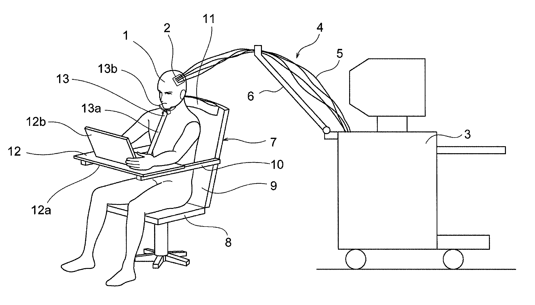
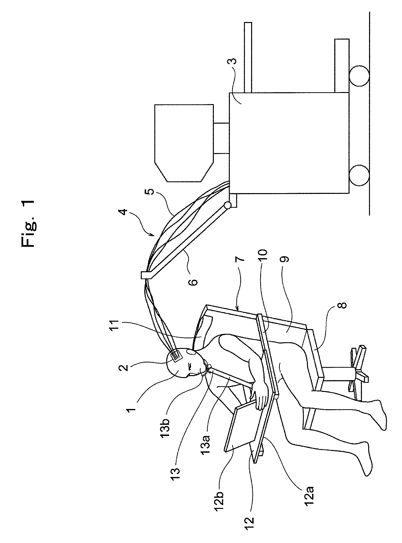
[0027]FIG. 1 is a perspective view including in part a side view showing a living body optical measurement apparatus representing one embodiment according to the present invention. In the drawing, at a head portion of a subject 1, a probe holder portion 2 is attached. The probe holder portion 2 is provided with a plurality (for example, 16 pieces) of optical measurement use probes (not shown) arranged in a grid shape.

[0028] A measurement apparatus main body 3 and the probe holder portion 2 are optically connected by a group of optical fibers 4. The group of optical fibers 4 contains a plurality (for example, 16 pieces) of optical fibers 5. A part of these optical fibers 5 are for irradiation use optical fibers for guiding detection light to the probes from the measurement apparatus main body 3, and the remaining optical fibers 5 are for light receiving use optical fibers for guiding the detection light reflected (scattered) within the subject 1 and transmitted therethrough to the m...

embodiment 2

[0040] Now, FIG. 6 is a perspective view showing a measurement chair in a living body optical measurement apparatus representing an embodiment 2 according to the present invention. In the drawing, the measurement chair 7 is provided via the desk 12 with a chest-abutting member 14, which is applied to the chest of the subject 1 and restricts a motion of upper part of the subject 1. The base end portion of the chest-abutting member 14 is swingablly connected to the horizontal portion 12a of the desk. By fastening a fastening member (not shown) provided for the chest abutting member 14, the inclination angle of the chest abutting member 14 can be kept at any angle.

[0041] Further, the measurement chair 7 is provided with a light shielding hood 15 for covering around the head portion of the subject 1. The light shielding hood 15 is rotatablly attached to the top end portion of the backrest portion 9. The light shielding hood 15 is made from a light shielding material such as a light shi...


PUM


Abstract

A measurement chair 7 is provided with a chair seat portion 8, a backrest portion 9, a pair of armrest portions 10, a pillow portion 11 provided at the upper portion of the backrest portion 9, a desk 12 provided on both armrest portions 10 and a jaw receiving portion which receives the jaw of the subject 1 and restricts a motion of the jaw. The pillow portion 11 receives the back head portion of the subject 1 and restricts a motion of the head of the subject 1. The desk 12 includes an inclined portion 12b arranged inclinedly with respect to a horizontal plane thereof. The jaw receiving portion 13 includes a telescope type column 13a of which base end portion is attached to a horizontal portion 12a of the desk 12 so as to permit free rotation in all directions and a contacting portion 13b which is provided at the top end portion of the column 13a for contacting the jaw. With such measurement chair of simple constitution, a motion of upper part of the subject is effectively restricted without giving the sense of oppression to the subject and a living body optical measurement apparatus, which permits a living body optical measurement with high measurement accuracy is obtained.

Description

FIELD OF THE INVENTION [0001] The present invention relates to a living body optical measurement apparatus which measures a reaction information within a living body by making use of light at the time when a subject is seated on a measurement chair and is caused to carry out a task of drawing such as letters and pictures or a task relating to such as the sense of sight and the sense of hearing. BACKGROUND ART [0002] There was a problem that during living body optical measurement, when a subject moves (body motion), such as an attachment position, angle or contact pressure of an optical fiber probe changes and a condition of optical passages change, thereby, the measurement accuracy reduces. [0003] For this reason, conventionally, when a living body optical measurement is performed, while a subject is seated, for example, on a general-purpose chair and is caused to carry out a task relating to such as the sense of sight and the sense of hearing, the living body optical measurement wa...

Claims


Application Information

Patent Timeline
IPC IPC(8): A61B5/00A61B5/02
CPCA61B5/702A61B5/0059
Inventor ISHIZUKA, TAKASHI
Owner HITACHI MEDICAL CORP
Learn More