
Electronic locking clutch with lock indication device

Inactive Publication Date: 2006-02-23
NTN CORP
View PDF13 Cites 3 Cited by
  • Summary
  • Abstract
  • Description
  • Claims
  • Application Information

AI Technical Summary

Benefits of technology

[0008] A first biasing element is supported on the retainer to radially bias the retainer position relative to the inner race such that each of the rollers is held in the center of the flat cammed surfaces on the inner race. An actuation disk is connected to the retainer by a means which allows some axial movement of the actuation disk with respect to the retainer toward the case end. The preferred method would include a series of retainer tabs extending axially from one end of the retainer and notches which are adapted to engage the retainer tabs, thereby preventing circumferential or relative rotational motion of the actuation disk relative to the retainer and allowing axial motion of the actuation disk relative to the retainer. There are at least two, and preferably four, tabs extending outward to engage notches within the actuation disk. A second biasing element is disposed between the actuation disk and the inner axial surface of the case end to bias the actuation disk away from the case end.
[0009] The clutch assembly includes an actuator to selectively overcome the second biasing element to force the actuation disk into contact with the case end, wherein rotation of the outer race and case end with respect to said inner race is frictionally transferred to the actuation disk and the retainer, overcoming the first biasing element, thereby moving the rollers along the ramp surfaces to a position where the rollers engage and wedge between the inner and outer races to prevent relative rotation between the inner and outer races.

Problems solved by technology

However, when traction is reduced or lost altogether at one or both wheels, a standard open differential assembly will cause one wheel to spin uselessly, providing little tractive power to the wheels.
For instance, if one tire is on ice or some other slippery surface and the other tire is on dry pavement, slip will occur at the low friction side and the torque applied to the non-slipping tire will be limited to the torque generated at the slipping tire.
In such circumstances, very little power will be delivered to the wheel on the dry pavement and the vehicle will not be powered forward or backward.

Method used


Image

  • Electronic locking clutch with lock indication device
  • Electronic locking clutch with lock indication device
  • Electronic locking clutch with lock indication device

Examples


Embodiment Construction

[0020] The following description of the preferred embodiment of the invention is not intended to limit the scope of the invention to this preferred embodiment, but rather to enable any person skilled in the art to make and use the invention.

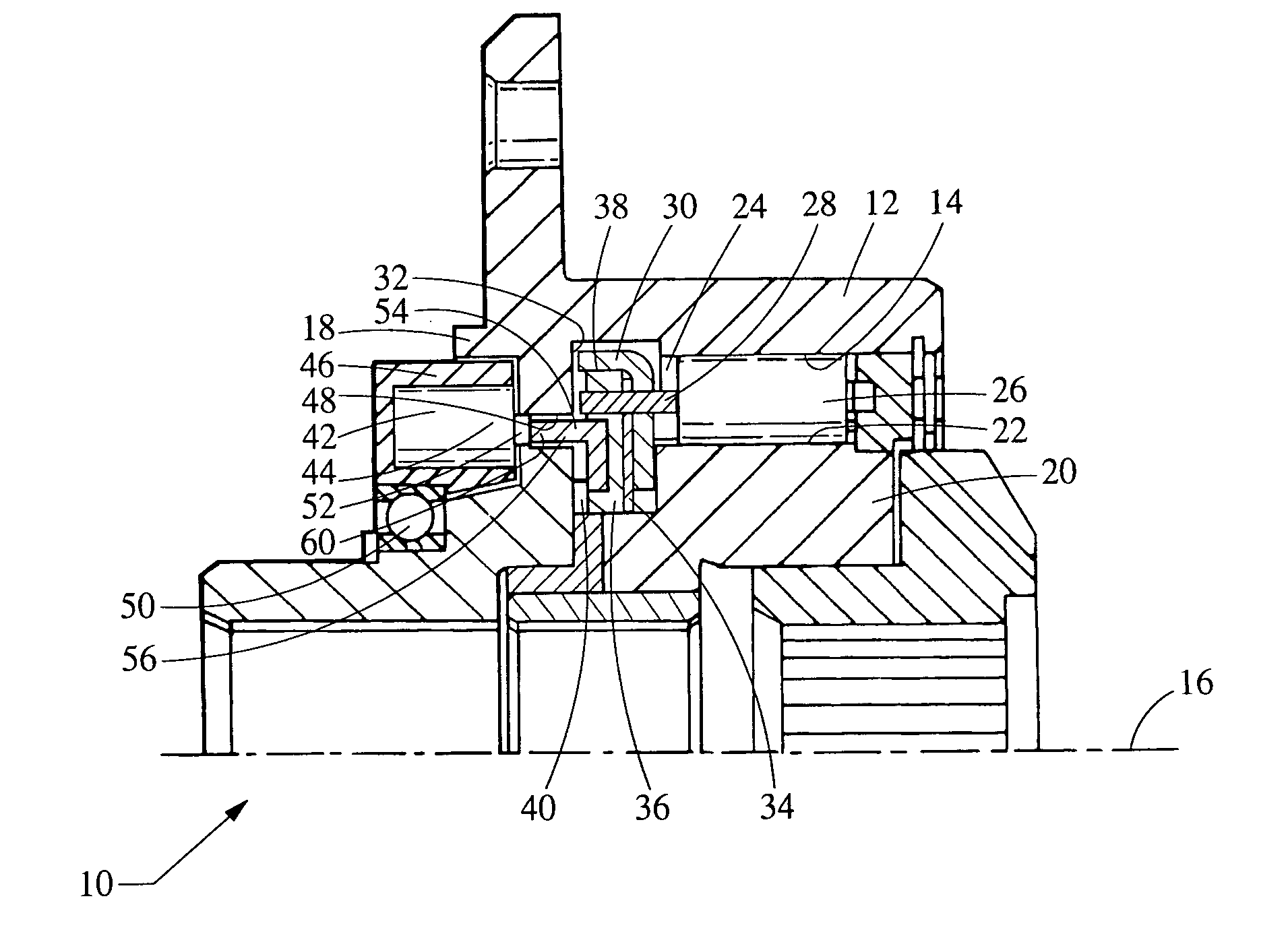
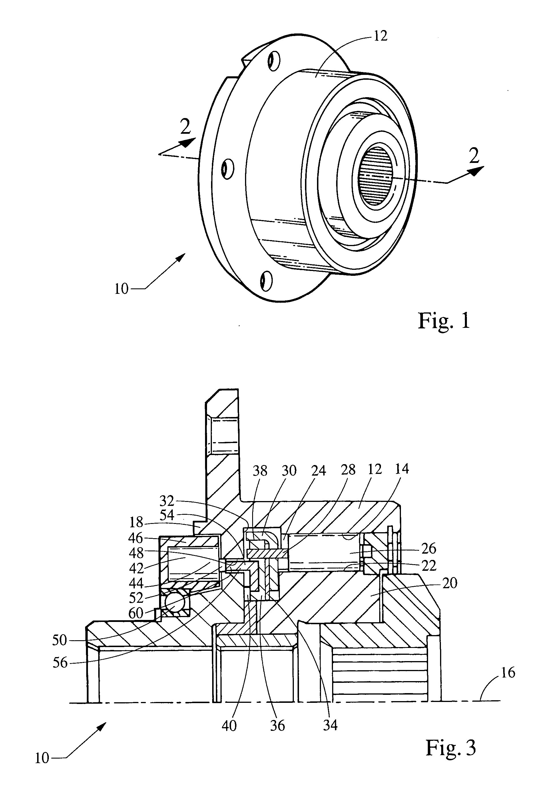
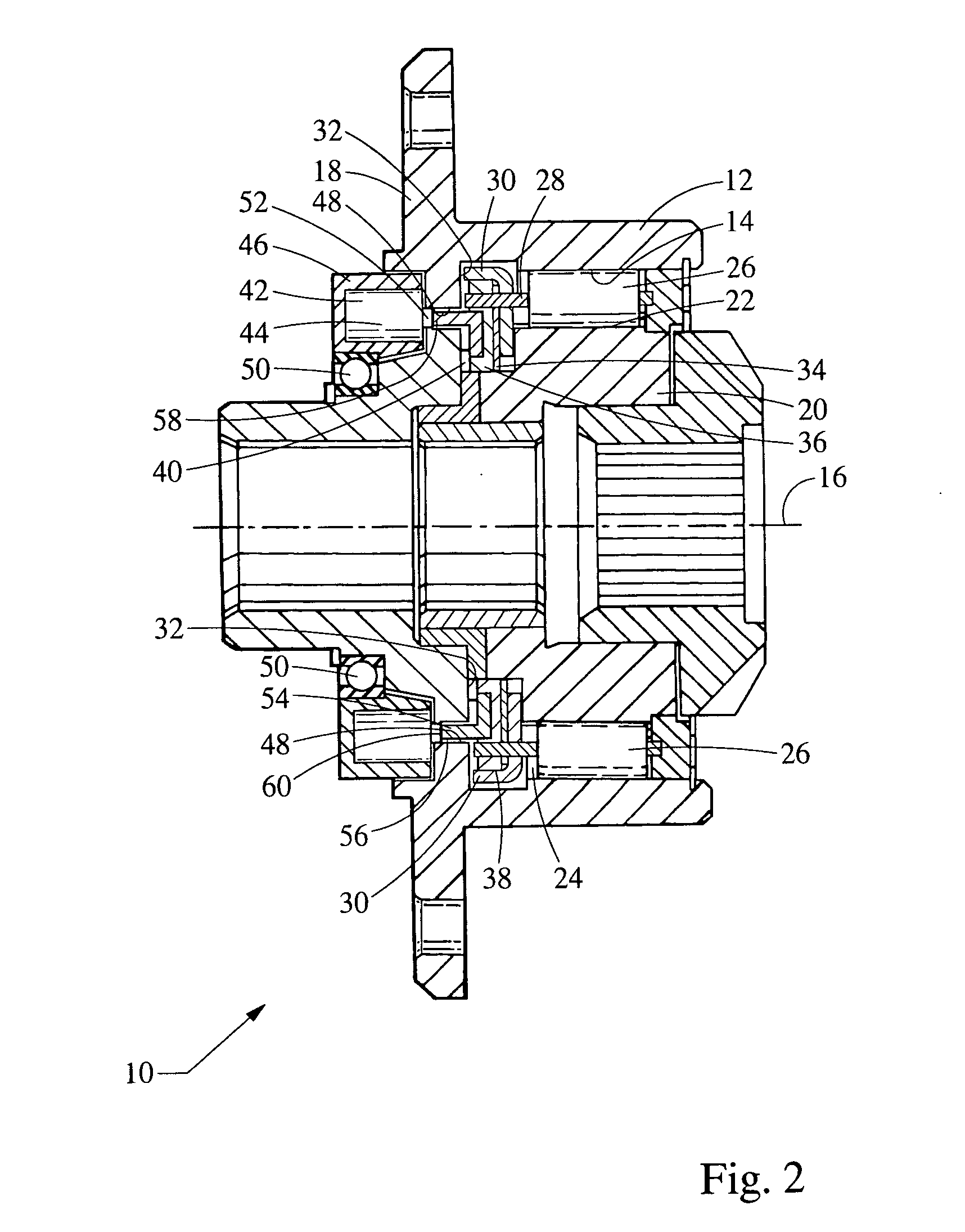
[0021] Referring to FIGS. 1-3, and over-running clutch of the present invention is shown generally at 10. The over-running clutch 10 includes an outer race 12 having an inner surface 14 that is rotatable about a first axis 16 and a case end 18. An inner race 20 includes a cammed outer surface 22 coaxial with the inner surface 14 of the outer race 12. The inner surface 14 of the outer race 12 and the outer surface 22 of the inner race 20 define a gap 24 between the inner race 20 and the outer race 12.

[0022] A plurality of rolling elements 26 are positioned within the gap 24. Preferably, the rolling elements 26, the inner race 20 and the outer race 12 are made from steel. Due to the high hertzian contact stresses experienced by the rolling elemen...


PUM


Abstract

An over-running clutch includes an outer race and an inner race defining a gap therebetween. A plurality of rolling elements are positioned between the inner and outer races. A retainer interconnects the rolling elements. A first biasing element biases the retainer to hold the rolling elements such that the inner and outer races are free to rotate relative to one another. An actuator selectively forces the rolling elements to a position where the rolling elements engage and wedge between the inner and outer races, thereby locking the clutch. A sensor is adapted to detect the engagement of the clutch and to send a corresponding signal.

Description

TECHNICAL FIELD OF THE INVENTION [0001] This invention is related to a two way over-running clutch. More specifically, the present invention relates to a two-way over-running clutch assembly of a roller / ramp variety, which includes a lock indication device that sends a signal to indicate if the over-running clutch is engaged. BACKGROUND OF THE INVENTION [0002] Differential assemblies are used in motor vehicles to allow the wheels to turn at different rotational speeds while still providing power to the wheels. Various types of differential assemblies are used to redirect the transfer of power to the driving axles. [0003] In a standard open differential, as a vehicle turns, power is provided through a pinion and ring gear to the differential housing. As the inner and outer wheels trace paths of different radii, side gears attached to right and left axle half shafts are allowed to turn at different speeds by their interconnection through intermediate spider gears, which rotate with th...

Claims


Application Information

Patent Timeline
IPC IPC(8): F16D41/06
CPCF16D43/204F16D7/06
Inventor MONAHAN, RUSSELLGOTO, SHIRO
Owner NTN CORP
Learn More