
Piping attachment for steam/condensate connections to dt trays

Inactive Publication Date: 2011-06-30
CROWN IRON WORKS
View PDF2 Cites 0 Cited by
  • Summary
  • Abstract
  • Description
  • Claims
  • Application Information

AI Technical Summary

Benefits of technology

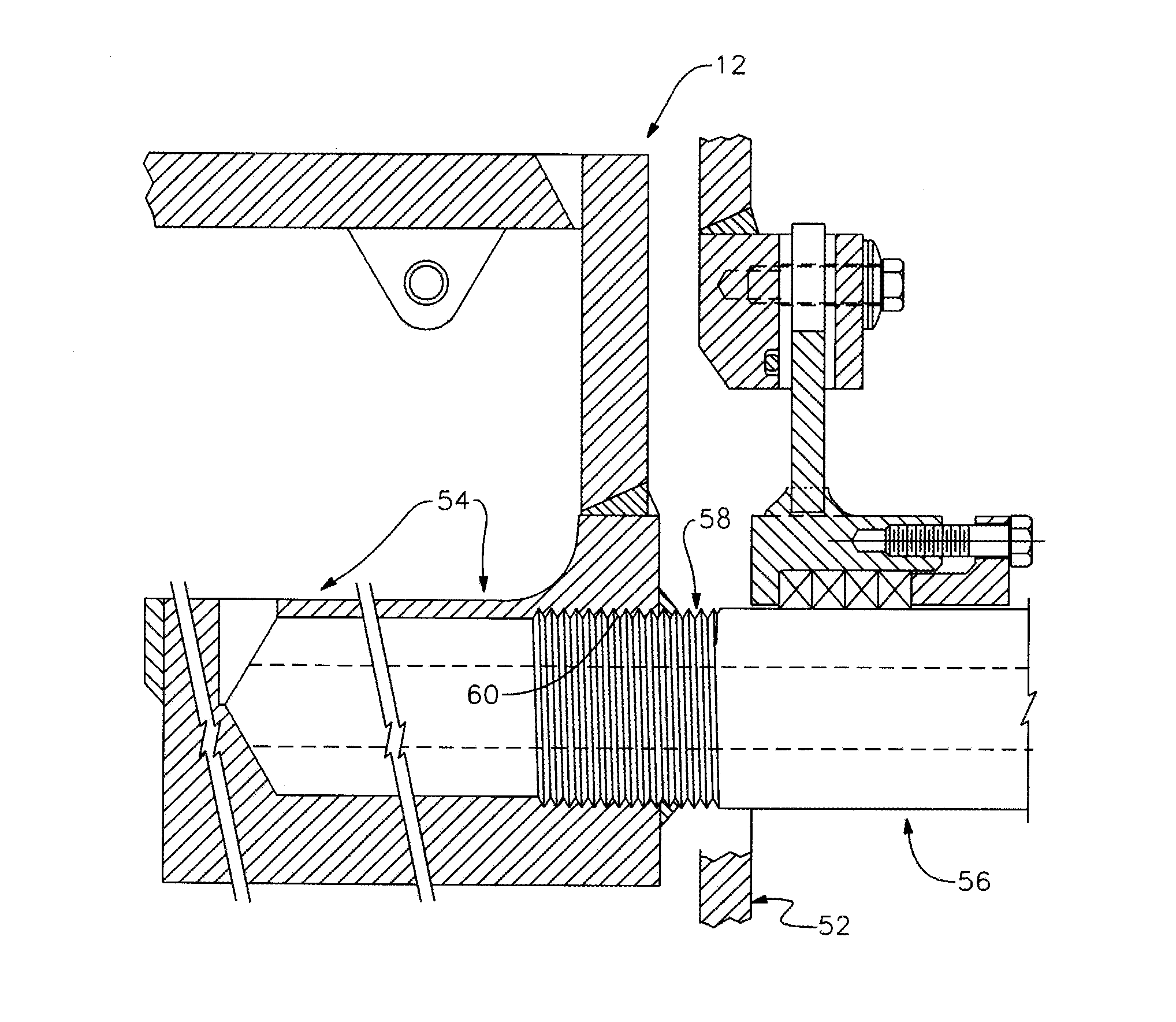
[0014]The present invention is a construction of a DT which facilitates introduction of live steam into chambers of the DT. The construction also facilitates egress of steam condensate from the chambers.
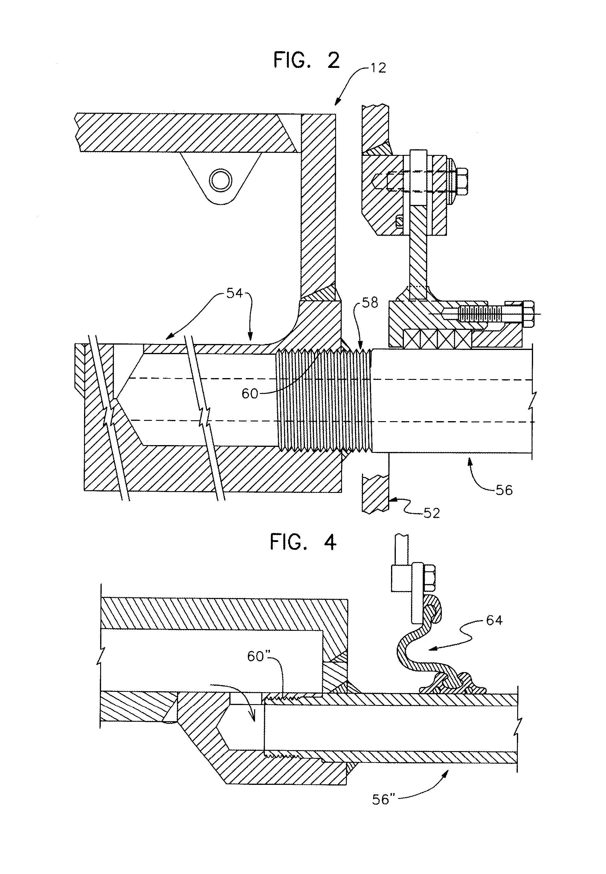
[0015]The invention comprises one or more attachments, which can be nipple-like in construction, each of which mates with one chamber port spaced angularly from the other ports in a DT chamber. The nipple-like construction renders the structure easily accessible. This is true because of the radially peripheral placement of the ports. The number of egress ports will vary depending upon the construction and application of the particular DT. Similarly, placement will vary depending upon the particular DT and its construction and application.

Problems solved by technology

Performance of these steps results in an oil-depleted meal and a liquid oil.
Accessibility to the compartments of the DT from the outside of the equipment can be difficult.
Repairs in various locations of the DT can, therefore, be difficult.
Repairs to condensate and steam lines can be quite slow.
With such prior art equipment, downtime can be significant.

Method used


Image

  • Piping attachment for steam/condensate connections to dt trays
  • Piping attachment for steam/condensate connections to dt trays
  • Piping attachment for steam/condensate connections to dt trays

Examples


Embodiment Construction

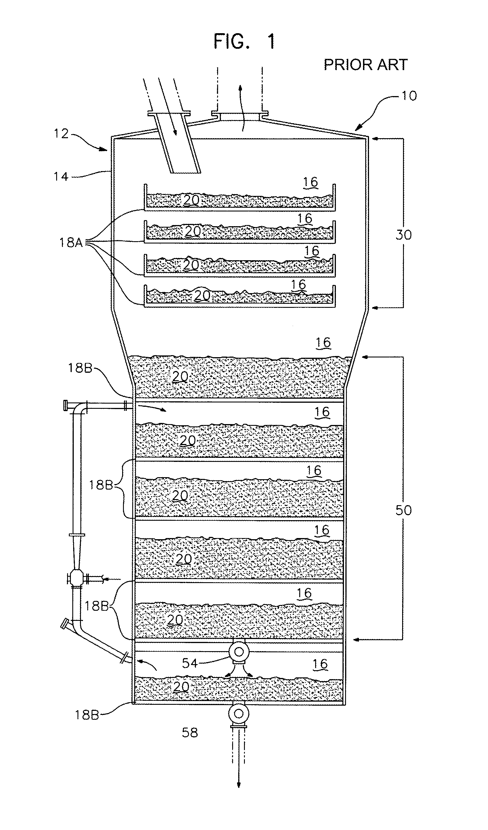
[0024]Referring now to the drawing figures, wherein like reference numerals denote like elements throughout the several views, FIG. 1 illustrates a desolventizer / toaster (DT) of the type to which the present invention is an improvement. A desolventizing apparatus 10 having a hollow, generally circularly cylindrical shaped housing 12 is shown. Housing 12 forms a vertical column 14 divided horizontally into a vertical series of compartments 16 by trays 18 for cascadingly carrying solvent-laden material 20. Each of the trays 18 has an opening through which the particulate material 20 is passed downwardly from one compartment to the next in a controlled manner. The column 14 can be equipped with agitation means, although such means are not illustrated. The agitation means, when used, maintain the particulate material occupying each tray in adequate mixing motion, to keep the particulate material in a loose, non-agglomerated and substantially homogeneous condition. Further, the agitation...


PUM


Abstract

A desolventizer / toaster (DT). The DT in accordance with the present invention is provided with a generally circularly cylindrical body formed with respect to a generally vertically extending axis. A plurality of substantially planar panels, generally perpendicular to the axis with respect to which the body is formed define a plurality of axially aligned chambers. Means, proximate a wall defining the generally circularly cylindrical body, are provided to afford ingress and egress into one or more of the chambers.

Description

CROSS-REFERENCE TO RELATED APPLICATIONS[0001]This is a regular application filed under 35 U.S.C. §111(a) claiming priority, under 35 U.S.C. §119(e) (1), of provisional application Ser. No. 61 / 266,021, previously filed Dec. 2, 2009 under 35 U.S.C. §111(b).TECHNICAL FIELD[0002]The present invention deals broadly with the field of processing granular material having a solvent entrained therein. More narrowly, however, it deals with equipments for removing solvent from a granular material, such as edible grains, where the solvent has been used to separate one portion of the grain from another. The specific focus of the invention is the construction of a desolventizer-toaster (DT) which affords various advantages over such equipments known in the prior art.BACKGROUND OF THE INVENTION[0003]Various solvents such as hexane, heptane and different alcohols are commonly used for treating granular solid materials to facilitate separation of one portion of the granular material from another. Typ...

Claims


Application Information

Patent Timeline
IPC IPC(8): F26B19/00
CPCF26B17/003F26B2200/06F26B25/10
Inventor ANDERSON, GEORGE E.
Owner CROWN IRON WORKS
Learn More