Method of manufacturing light-alloy wheel for vehicle and the wheel

a technology of light alloys and wheels, applied in the field of manufacturing a light alloy automotive wheel, can solve the problems of increasing the weight of the rim, increasing the unsprung weight, and affecting the steering performance, so as to facilitate the ingress and egress of casting cores or drills, reduce thermal strain, and facilitate cutting.

Inactive Publication Date: 2007-04-19
WASHI KOSAN
View PDF4 Cites 1 Cited by
  • Summary
  • Abstract
  • Description
  • Claims
  • Application Information

AI Technical Summary

Benefits of technology

[0015] According to the first aspect of the invention, when forming the hollow portion in the spoke portion and / or the rim portion of the wheel, the ingress and egress of casting cores or a drill is facilitated, since the bead seat portion is constructed so as to be integrated with the rim flange along one edge portion while being joined to the rim well rising portion only along the other edge portion thereof, a strong connecting portion is configured on the rim flange without imparting any effect on the metallic compositions by welding, and since there is only one welding location, thermal strain is reduced. In addition, since the rim well rising portion and the bead seat portion are formed individually, there are provided advantages that cutting is facilitated and that the rim flange does not have to be bent to fall in the L shape in section to thereby increase the machining accuracy. Cutting and spinning processes can be simplified so as to reduce the production costs.
[0016] According to the second aspect of the invention, since the bead seat is formed by joining the annular patch thereto in a post-process to facilitate the ingress and egress of a casting core or a drill which is used to form a hollow portion in the spoke portion and / or the rim portion of the wheel, a number of steps of cutting and spinning can be omitted, thereby making it possible not only to increase the machining accuracy but also to reduce the production costs.

Problems solved by technology

Although the thickness of the rim only has to be increased in order to increase the rigidity of the rim, increasing the thickness results in an increase in weight of the rim and an increase in unsprung weight, leading to a risk that the steering performance is lost remarkably.

Method used


Image

  • Method of manufacturing light-alloy wheel for vehicle and the wheel
  • Method of manufacturing light-alloy wheel for vehicle and the wheel
  • Method of manufacturing light-alloy wheel for vehicle and the wheel

Examples


embodiment 1

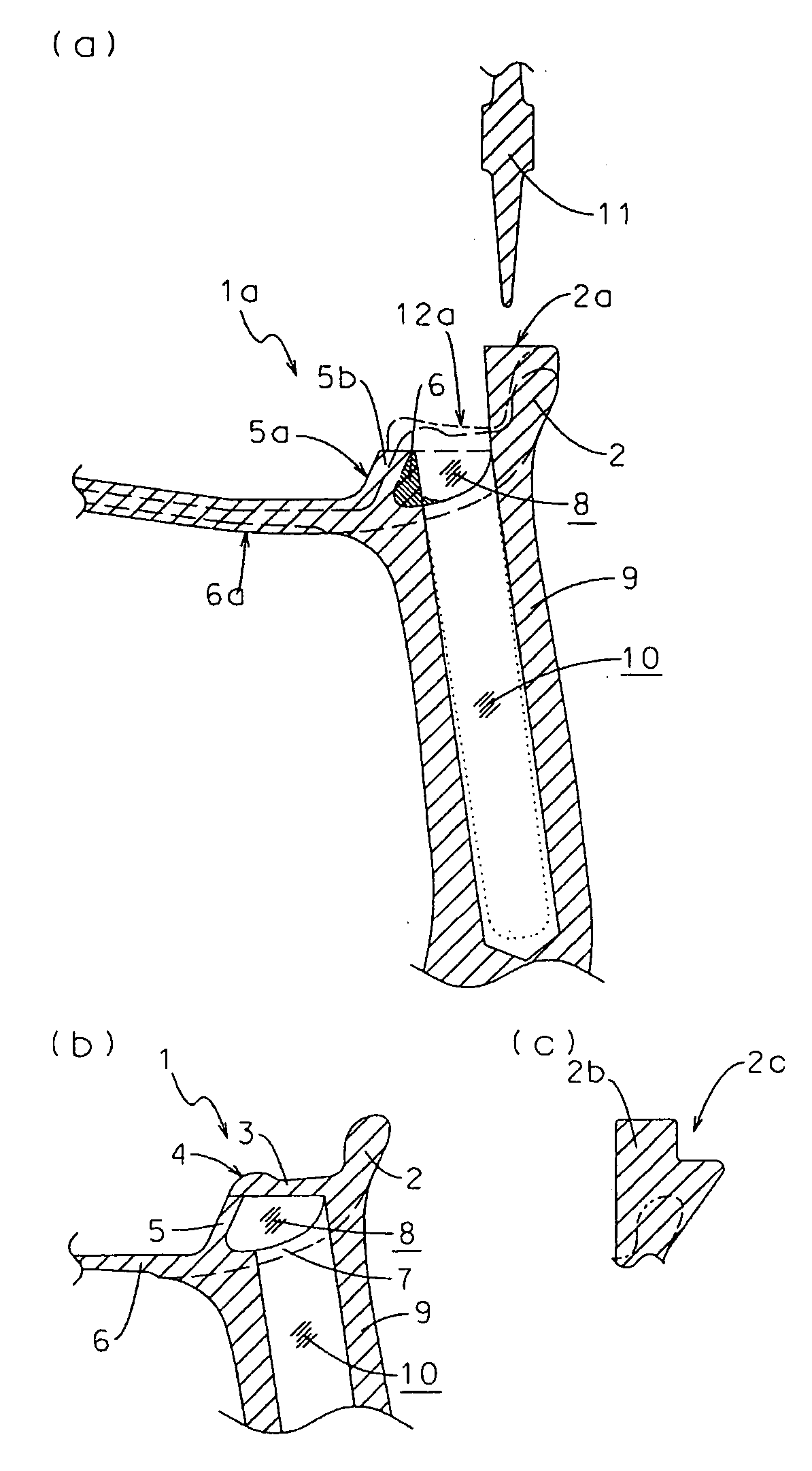
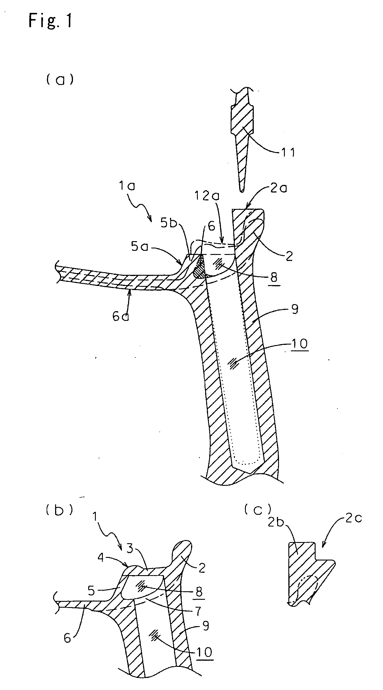
[0018]FIG. 1(b) is a sectional view of a completed outer rim portion 1, wherein reference numeral 2 denotes an outer rim flange, 3 a bead seat, 4 a hump, 5 a rim well rising portion, 6 a rim well, 7 a rim outer shell portion, and 8 an annular hollow portion. Reference numeral 9 denotes a spoke, which makes up a disc portion. Reference numeral 10 denotes a spoke hollow portion, which is formed using a core in the case of casting, or by machining the sport firstly formed solid using a drill or the like.

[0019]FIG. 1(a) is a sectional view showing a cast outer rim material 1a, and a spoke hollow portion 10 is formed by drilling. A broken line shows a hollow portion that is to be formed using a core during casting. Compared to an outer rim flange 2, an excess thickness is formed on a flange precursor 2a for forming the outer rim flange 2. In addition, an annular flange molded body 5a for forming a rim well rising portion 5 has a trapezoidal cross section and makes up a rim well rising p...

embodiment 2

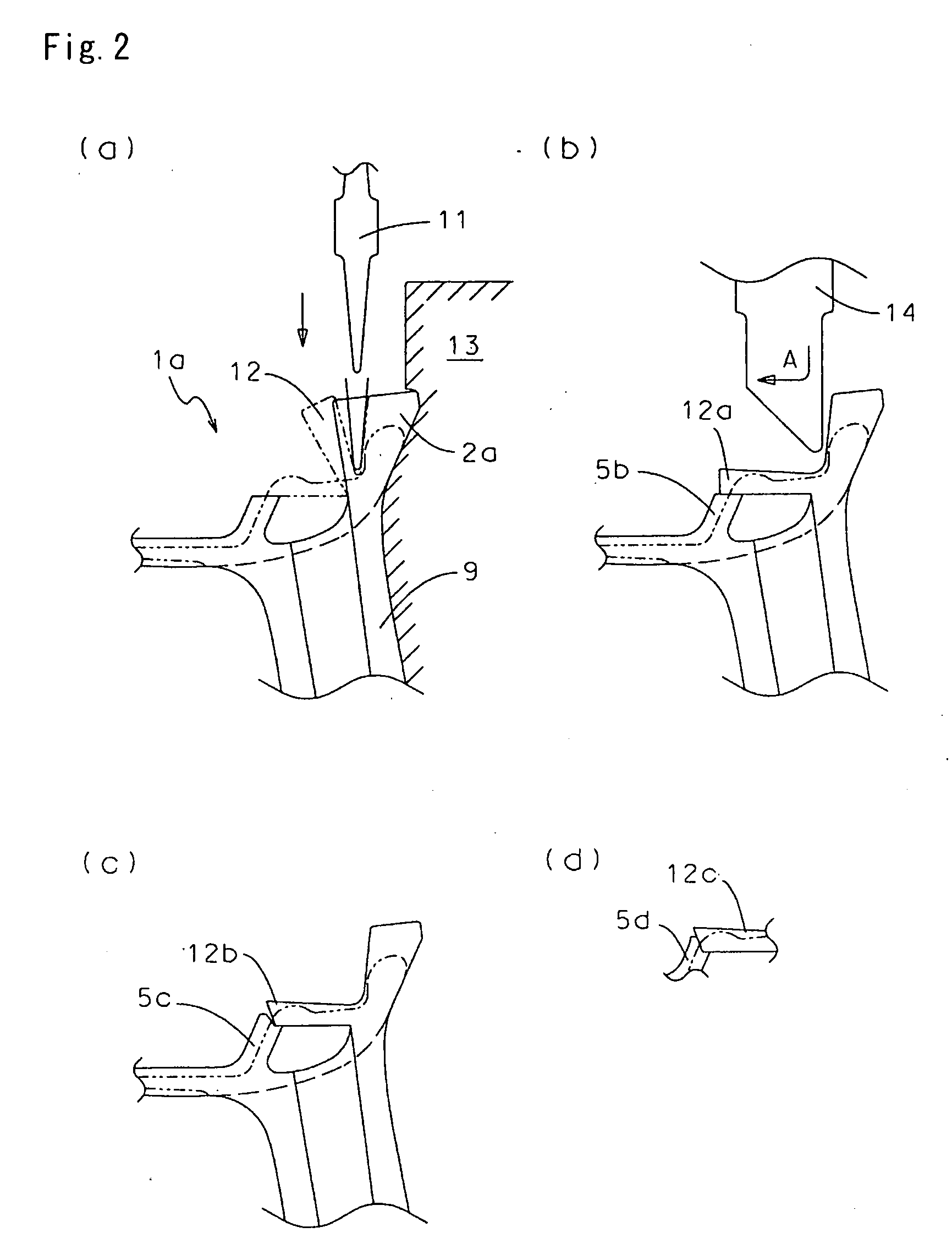
[0021]FIG. 3 shows how to manufacture the outer rim 1 using a forging method. FIG. 3(a) is a vertical sectional view showing a state in which when forging a spoke portion 9, an outer rim precursor 15 is forged integrally with the spoke portion 9, an outer rim portion which will be completed being shown by chain lines. FIG. 3(b) shows a state in which spinning is applied to the outer rim precursor 15, so as to form a flange precursor 2b, a rim well precursor 6b and a rim well rising precursor 5c. Furthermore, drilling for making a hole is applied to the spoke portion 9 to form a spoke hollow portion 10, and a hatched portion 6a is cut to be removed along the full circumference thereof so as to form an internal surface of the rim well rising portion precursor 5c. FIG. 3(c) shows a state in which a groove 16 is cut in the flange precursor 2b, and the spinning roller 11 is then pressed against the groove 16 so formed, so as to form the bead seat precursor 12a in the manner that has been...

embodiment 3

[0022] In preparing an outer rim portion 1 having an annular hollow portion provided therein, another mode for carrying out the invention will be described with respect to the arrangement of a predetermined amount of material and shape thereof for forming an outer and inner rims on a circumferential edge of a disc portion such as a spoke to which a certain design is imparted. FIG. 4(a) shows a cross section of a rim precursor 15a which is forged or cast, and hatching is imparted thereto. In the case of the rim precursor 15a being forged, drilling is applied to a spoke 9a which makes up a disc portion so as to form a spoke hollow portion 10a. In the case of the rim precursor 15a being cast, a core may be used to form the spoke hollow portion 10a. The spinning roller 11 is brought into press contact with the rim precursor 15a so as to tear it open, and part of the rim precursor is caused to fall in a sloping fashion to a position indicated by a chain double-dashed line. Furthermore, a...


PUM

PropertyMeasurementUnit
widthaaaaaaaaaa
thicknessaaaaaaaaaa
diameteraaaaaaaaaa

Abstract

An outer rim molded material is molded by forging or casting, a portion of the outer rim which extends from a hump to a bead seat is separated from part of a rim flange precursor 2a and is caused to fall in a sloping fashion inwards of a wheel width so as to form a bead seat precursor 12a, and the bead seat precursor 12a so formed is then joined to be welded to a top or side of a rim well rising portion precursor 5b. An external surface is cut to be finished to a proper shape, and an annular hollow portion 8 is formed underneath a lower surface of the bead seat portion.

Description

TECHNICAL FIELD [0001] The present invention relates to a method for manufacturing a light alloy automotive wheel having an annular hollow portion provided in an outer rim portion thereof, and a wheel manufactured by the method. BACKGROUND ART [0002] As light alloy automotive wheels which are made of materials such as aluminum and magnesium are light in weight and good in machinability, wheels having superior designs have been provided, and the mounting ratio of such light alloy automotive wheels is so increased that they are mounted on production lines. However, external shapes of outer rims, such as shapes of a bead seat, a hump, a slope from the hump to a rim well and an inner surface of a rim flange, on which a tire is mounted, are regulated by the international standard made by European Tire and Rim Technical Organization (ETRTO), and in order to secure a regulated rigidity at these portions of a rim, the rim is constructed to have a certain thickness. Although the thickness of...

Claims


Application Information

Patent Timeline
Patent Type & Authority Applications(United States)
IPC IPC(8): B21D53/26B60B1/06B60B3/00B60B21/02
CPCB21D53/26B60B3/06Y10T29/49908Y10T29/49496Y10T29/49481Y10T29/49524Y10T29/49531Y10T29/49504Y10T29/49503
Inventor YOSHIMURA, KATSUNORI
Owner WASHI KOSAN
Why Eureka
Try Eureka