Vacuum circuit breaker

Active Publication Date: 2011-06-30
LS IND SYETEMS CO LTD
View PDF5 Cites 17 Cited by
  • Summary
  • Abstract
  • Description
  • Claims
  • Application Information

AI Technical Summary

Benefits of technology

[0020]Therefore, an object of the present invention is to provide a vacuum circuit breaker capable of enhancing an insulation ch

Problems solved by technology

Firstly, one main circuit unit 20 is implemented by assembling the epoxy housing 21, the vacuum interrupter 22, the upper conductor 23 and the lower conductor 24 to one another. This may increase fabrication time and may cause assembly errors.
Secondly, the frame unit 30 is eccentrically installed to the right side or the left side with respect to the driving unit 10

Method used


Image

  • Vacuum circuit breaker
  • Vacuum circuit breaker
  • Vacuum circuit breaker

Examples


Embodiment Construction

[0032]Description will now be given in detail of the present invention, with reference to the accompanying drawings.

[0033]For the sake of brief description with reference to the drawings, the same or equivalent components will be provided with the same reference numbers, and description thereof will not be repeated.

[0034]Hereinafter, a vacuum circuit breaker according to the present invention will be explained in more detail with reference to the attached drawings.

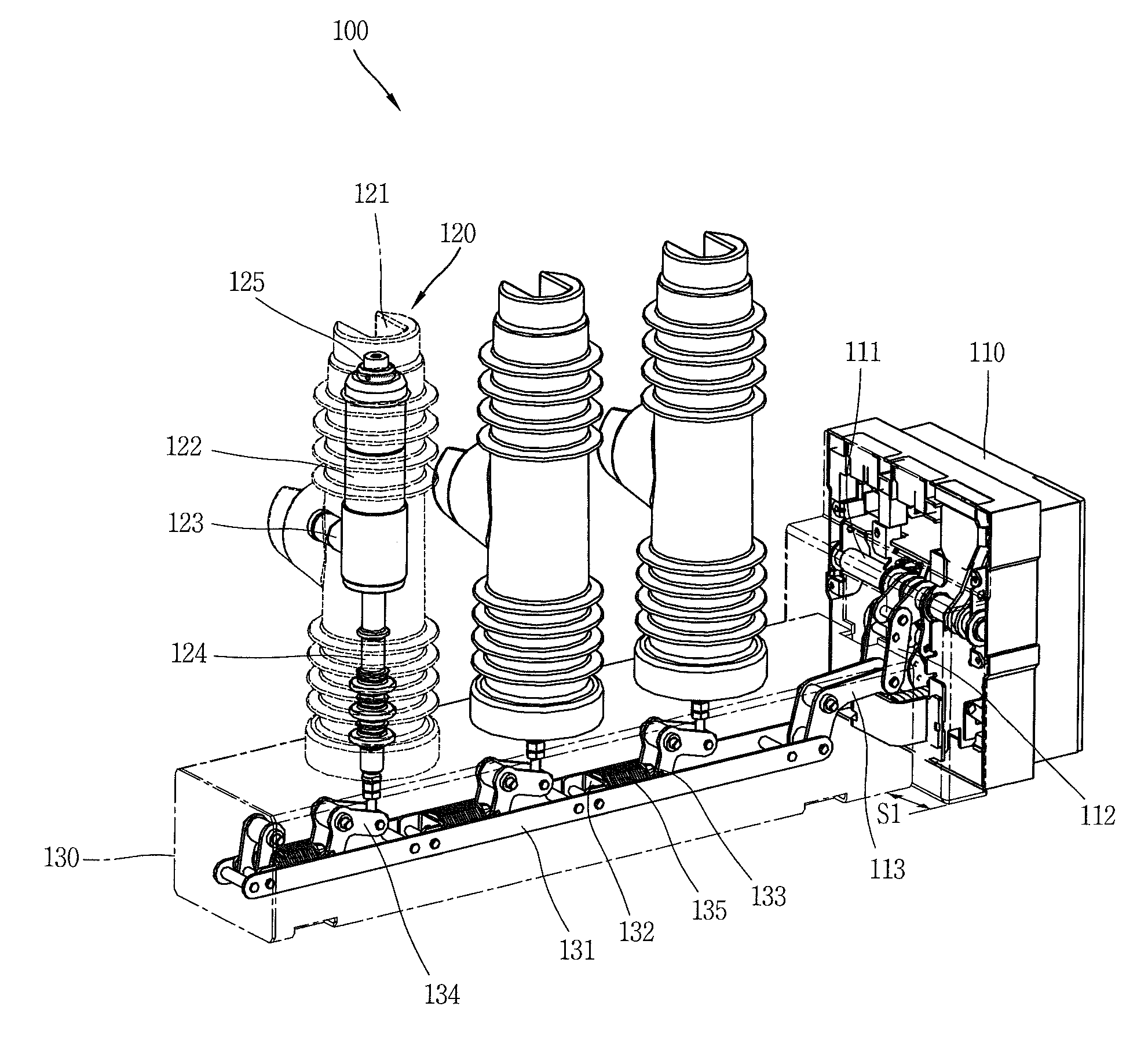
[0035]FIG. 3 is a perspective view of a vacuum circuit breaker according to a preferred embodiment of the present invention, FIG. 4 is a perspective view of the vacuum circuit breaker of FIG. 3, which is shown from a different angle from FIG. 3, FIG. 5 is a sectional view of main circuit units of the vacuum circuit breaker of FIG. 4, which is taken along line ‘I-I’ in FIG. 4, and FIG. 6 is a planar view of the vacuum circuit breaker of FIG. 3.

[0036]As shown, a vacuum circuit breaker 100 according to the present invention c...


PUM


Abstract

Disclosed is a vacuum circuit breaker. As a plurality of components of main circuit units are integrally formed as one module by molding using epoxy, the main circuit units are easily fabricated, and assembly errors are prevented. Since the main circuit units are arranged to be symmetrical to each other based on a driving unit, an insulation distance between a switchgear and the main circuit units can be obtained without increasing a size of the switchgear. This may allow the main circuit units to be easily arranged at the right side or at the left side according to an installation state of the switchgear.

Description

CROSS-REFERENCE TO a RELATED APPLICATION[0001]Pursuant to 35 U.S.C. § 119(a), this application claims the benefit of earlier filing date and right of priority to Korean Application 10-2009-0136236, filed on Dec. 31, 2009, the content of which is incorporated by reference herein in its entirety.BACKGROUND OF THE INVENTION[0002]1. Field of the Invention[0003]The present invention relates to a vacuum circuit breaker, and particularly, to a vacuum circuit breaker capable of molding a vacuum interrupter by epoxy, and symmetrically arranging main circuit units at a center portion of a driving unit.[0004]2. Background of the Invention[0005]A switchgear serves to monitor or control or protect an electricity system used to transmit or to distribute power received from a power plant or a substation to a house. This switchgear consists of a structure for supporting or protecting unitary devices (circuit breaker, protection relay, etc.) attached thereto, and wires for connecting the unitary dev...

Claims


Application Information

Patent Timeline
IPC IPC(8): H01H33/666
CPCH01H33/022H01H33/66207H01H2033/6667H01H2033/6623H01H33/666
Inventor LEE, DONG SIK
Owner LS IND SYETEMS CO LTD
Why Eureka
Try Eureka