Magnetic drive

Inactive Publication Date: 2011-06-30
SVM SCHULTZ VERW
View PDF14 Cites 7 Cited by
  • Summary
  • Abstract
  • Description
  • Claims
  • Application Information

AI Technical Summary

Benefits of technology

[0009]Therefore it is an object of the invention to avoid at least one of the before-mentioned disadvantages, in particular to provide a magnetic drive that switches faster.
[0010]This problem is solved by a magnetic drive as described in the beginning where it is suggested that the hinged armature is formed by an armature support carrying a magnetic armature part that interacts with the magnetic body. The invention suggests a basically two-part hinged armature formed by an armature support that receives the magnetic armature part. This solution leads to a surprisingly large number of advantages.
[0011]The suggestion according to the invention allows, first of all, to realize the hinged armature significantly lighter with identical magnetic qualities what leads, because of the lower mass to be accelerated, while the attracting power generated by the body remains the same, to a higher acceleration and therefore to lower switching times. The suggestion according to the invention allows furthermore employing the rather expensive magnetic material of the hinged armature effectively. Namely only in the area where it is perfectly positioned and highly efficient in interaction with the magnetizable body a magnetic armature part is arranged on the hinged armature according to the invention. In particular, also a suitable magnetic armature part is used for locking the magnetic flow. However, this determines a sufficient size of the magnetic armature part, and therefore a suitably smaller mass of the magnetic material of the hinged armature. The rather expensive material can be saved.

Problems solved by technology

Basically it is possible with increased effort, for example with a bigger coil or a larger number of windings on the coil, to increase the attracting effect of the solenoid, and thus the accelerating force on the hinged armature, however, this is accompanied also by a suitably increased effort (and therefore costs) and a higher weight and constructive volume.

Method used


Image

  • Magnetic drive
  • Magnetic drive
  • Magnetic drive

Examples


Embodiment Construction

[0034]In the figures identical or corresponding elements each are indicated by the same reference numbers and therefore are, if not useful, not described anew.

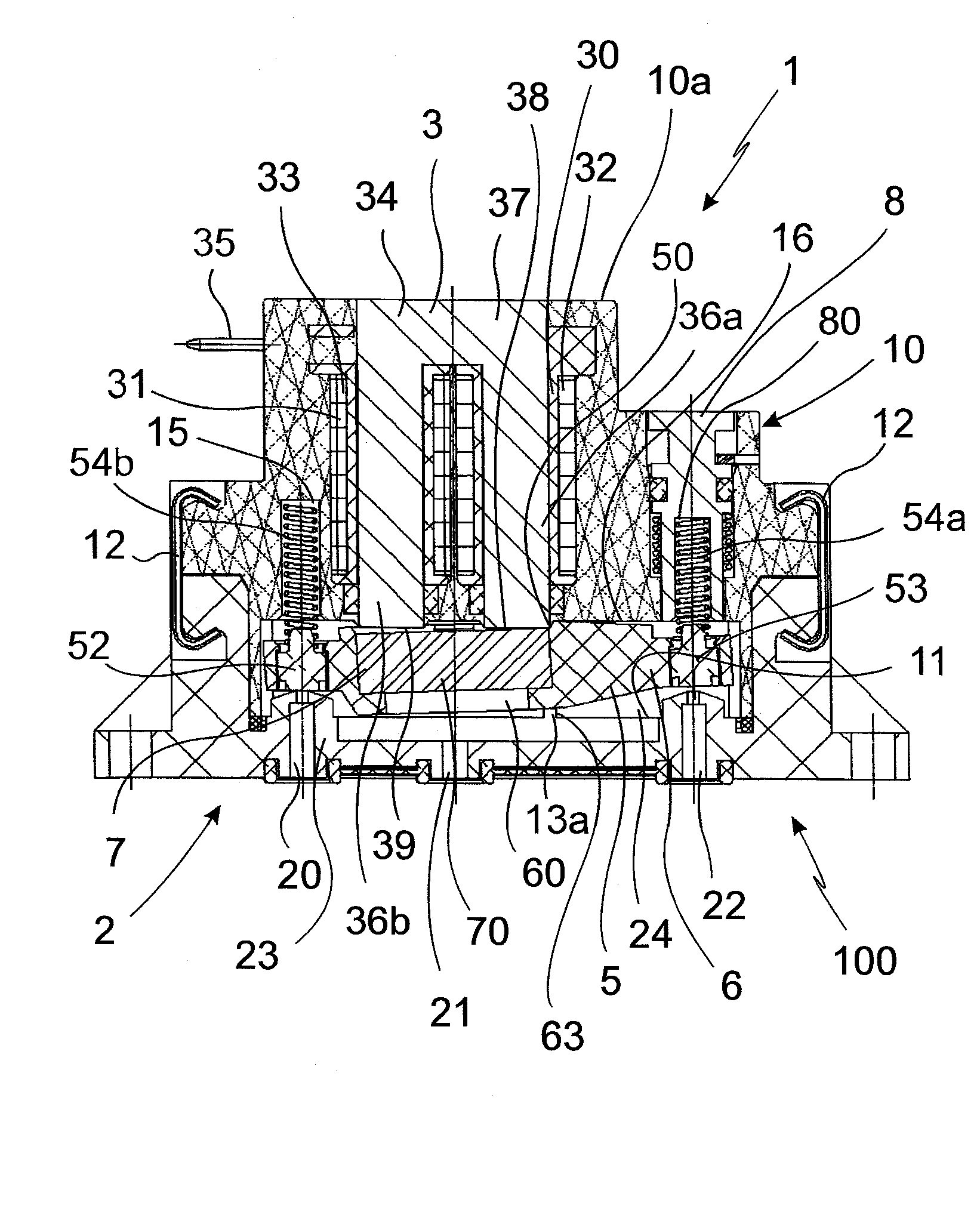
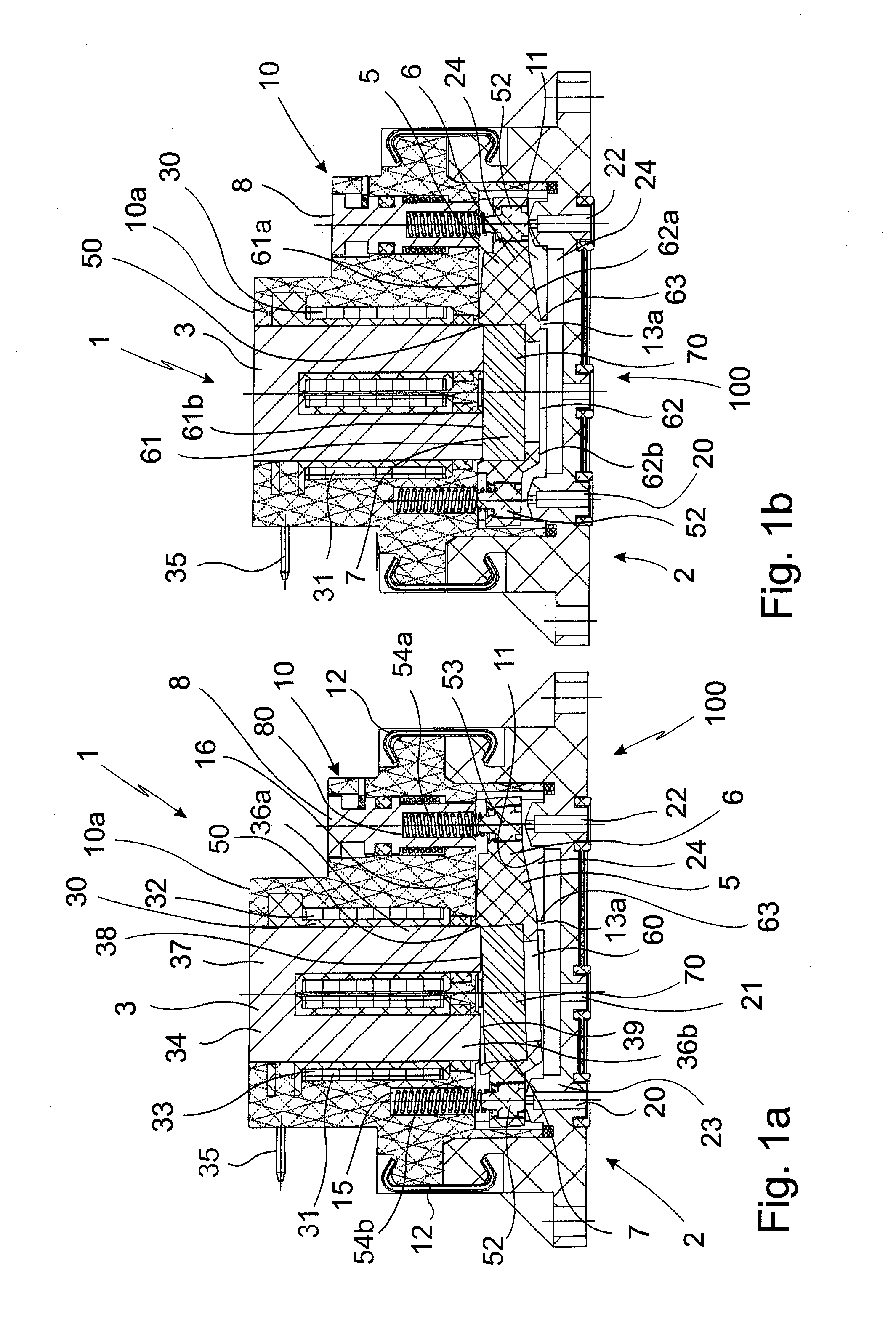
[0035]The magnetic valve 100 according to the invention is in an example in FIG. 1a. Roughly, the magnetic valve 100 according to the invention consists of the magnetic drive 1, and the valve housing 2 arranged on the bottom side (however, this may also be on the top side seen in technical respect), receiving several medium connections which run in the passage openings 20, 21,22.

[0036]In each of the modifications shown in these examples the left passage opening 20 serves as link of the pressure line, the centrally arranged passage opening 21 is connected with the working connection, the passage opening 22 arranged on the right hand side serves as link to the ventilation line. The passage opening 20 associated with the pressure line on the left hand side and the passage opening 22 arranged on the right hand side and associated ...


PUM


Abstract

The invention refers to a magnetic drive comprising a magnetizable body and an at least partly magnetic hinged armature. Depending on the degree of magnetization of the magnetizable body the hinged armature can take at least two different positions on the body. The hinged armature is formed by an armature support carrying a magnetic armature part.

Description

[0001]The invention refers to a magnetic drive comprising a magnetizable body and an at least partly magnetizable hinged armature, wherein the hinged armature on the body is able to take at least two different positions depending on the degree of magnetization of the magnetic body for what the hinged armature folds over a hinge axis.[0002]Furthermore the invention comprises also a magnetic valve that comprises a magnetic drive as described.BACKGROUND OF THE INVENTION[0003]Above-mentioned magnetic drives or magnetic valves are known in the state of the art. Thus, the German specification 44 05 657 describes a special magnetic valve where the hinged armature is equipped with two tappets spaced apart that interact in a suitable way with the passage openings of the valve. Depending on the position of the hinged armature, for example, one passage opening is released and the other is closed and vice versa. The arrangement is, for example, chosen such that in a first position the pressure ...

Claims


Application Information

Patent Timeline
IPC IPC(8): F16K31/08
CPCF16K31/06F16K31/0682F16K31/082
Inventor WEISS, JOHANN
Owner SVM SCHULTZ VERW
Why Eureka
Try Eureka