Charged particle beam system and method

Active Publication Date: 2019-11-21
CARL ZEISS MULTISEM GMBH
View PDF0 Cites 26 Cited by
  • Summary
  • Abstract
  • Description
  • Claims
  • Application Information

AI Technical Summary

Benefits of technology

This patent describes a technology to make high-frequency adjustments to a charged particle beam, which is used in microsystems. The technology allows for multiple adjustments to be made while the beam is scanned across a surface. The patent also describes how to detect the current in an angle-resolved manner, which can help with centering and aligning the beam. This technology can help improve the accuracy and efficiency of microsystems.

Problems solved by technology

Thereby, the imaging to separate detectors can become perturbed to an extent that a viable scan of the surface is not possible.
Common methods for charge mitigation in scanning electron microscopes (SEM) are not straightforward to adapt to both the primary and secondary beam path of a multi beam scanning beam system, especially with respect to the extraction field homogeneity constraints for good secondary imaging.
Available methods to realign the detectors in steady-state cases (i.e. between workflow runs or between recording of image frames) are not fast enough to steer the beams in a multi beam charged particle beam system.

Method used


Image

  • Charged particle beam system and method
  • Charged particle beam system and method
  • Charged particle beam system and method

Examples


Embodiment Construction

[0048]In the exemplary embodiments described below, components similar in function and structure are indicated as far as possible by similar reference numerals.

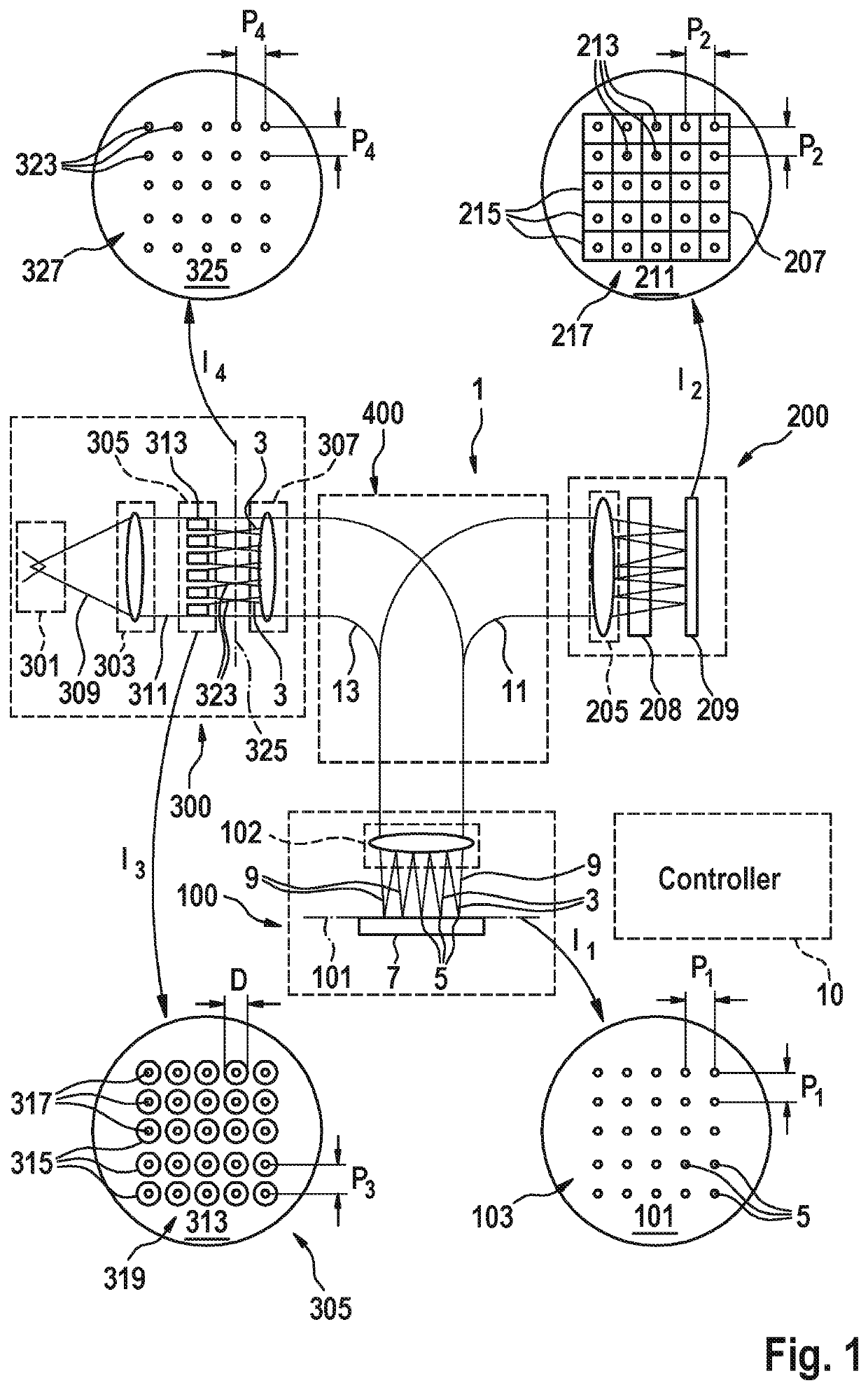
[0049]The schematic representation of FIG. 1 illustrates basic features and functions of a multi-beamlet charged-particle microscopy system 1. It is to be noted that the symbols used in the Figure do not represent physical configurations of the illustrated components but have been chosen to symbolize their respective functionality. The type of system shown is that of a scanning electron microscope (SEM) using a plurality of primary electron beamlets 3 for generating primary electron beam spots 5 on a surface of an object 7 located in an object plane 101 of an objective lens 102. It goes however without saying that the features and functions of system 1 can also be implemented using instead of electrons other types of primary charged particles such as ions and in particular helium ions, positrons, muons, and others.

[0050]The m...


PUM


Abstract

A charged particle beam system includes a charged particle source, a multi beam generator, an objective lens, a projection system, and a detector system. The projection system includes a first subcomponent configured to provide low frequency adjustments, and the projection system comprises a second subcomponent configured to provide a high frequency adjustments.

Description

FIELD[0001]The present disclosure relates to charged particle beam systems and methods. More particularly, the present disclosure relates to a multi beam charged particle beam system and related methods.BACKGROUND[0002]A multi beam charged particle beam system is disclosed, for example, in WO2005024881A2 and in WO2016 / 124648.[0003]For multi beam charged particle beam systems, such as multi beam electron microscopes, interaction products, i.e. secondary electrons, originating from different primary charged particle beams are often imaged onto separate detectors by a projection system. To this end, electrostatic extraction fields can be used. A homogeneous extraction field helps the imaging of the interaction products, such as secondary electrons, onto individual detectors of a multi detector and that a mapping between scan deflector voltages and respective beam positions at the individual detectors of the multi detector is faithful. The spot shape of the secondary electrons at the in...

Claims


Application Information

Patent Timeline
IPC IPC(8): H01J37/09H01J37/10H01J37/244H01J37/22H01J37/28H01J37/147
CPCH01J37/244H01J37/28H01J37/222H01J2237/1536H01J2237/0044H01J37/09H01J37/147H01J37/10
Inventor RIEDESEL, CHRISTOPHZEIDLER, DIRK
Owner CARL ZEISS MULTISEM GMBH
Why Eureka
Try Eureka