Non-contact holder and non-contact holding hand

a non-contact, holding hand technology, applied in the direction of work holders, manufacturing tools, etc., can solve the problems of unstable posture of workpieces, difficult to remain the same distance between workpieces and holding surfaces and forming a relatively large area within the plane of holding surfaces. achieve the effect of secure stabilization

Inactive Publication Date: 2011-06-30
SEIKO EPSON CORP
View PDF9 Cites 10 Cited by
  • Summary
  • Abstract
  • Description
  • Claims
  • Application Information

AI Technical Summary

Benefits of technology

[0009]An advantage of some aspects of the invention is to provide a non-contact holder and a non-contact holding hand capable of stabilizing the posture of a workpiece to be held.

Problems solved by technology

When the distribution of the surface roughness is greatly unbalanced within the plane of the holding surface, for example, an area producing a relatively large pressure loss is formed within the plane of the holding surface.
When the negative pressure acting on the workpiece varies or the positive pressure locally changes as described above, the distance between the workpiece and the holding surface is difficult to remain the same within the plane of the holding surface.
In this case, the posture of the workpiece becomes unstable.
In this case, the posture of the held workpiece becomes further unstable.

Method used


Image

  • Non-contact holder and non-contact holding hand
  • Non-contact holder and non-contact holding hand
  • Non-contact holder and non-contact holding hand

Examples


Embodiment Construction

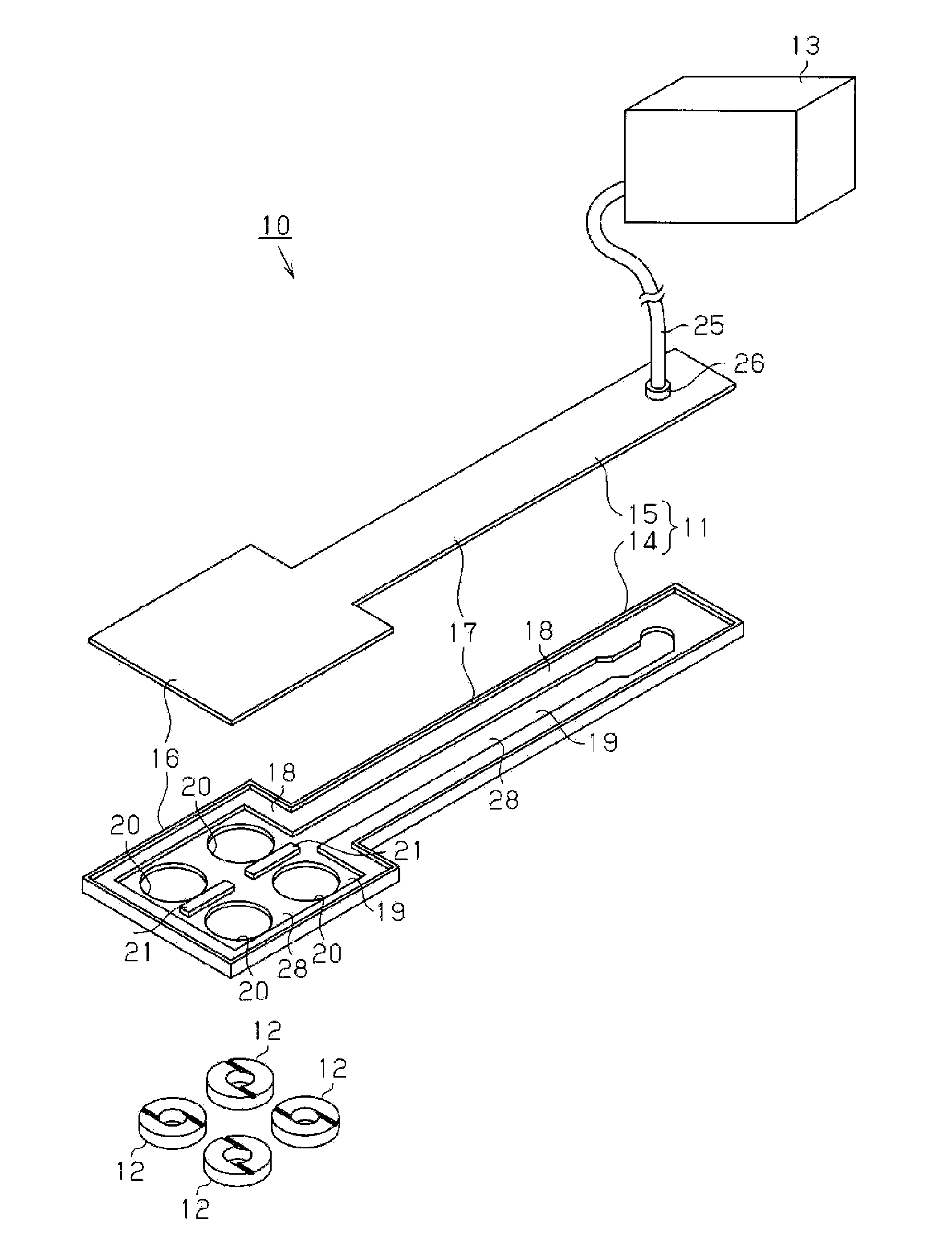
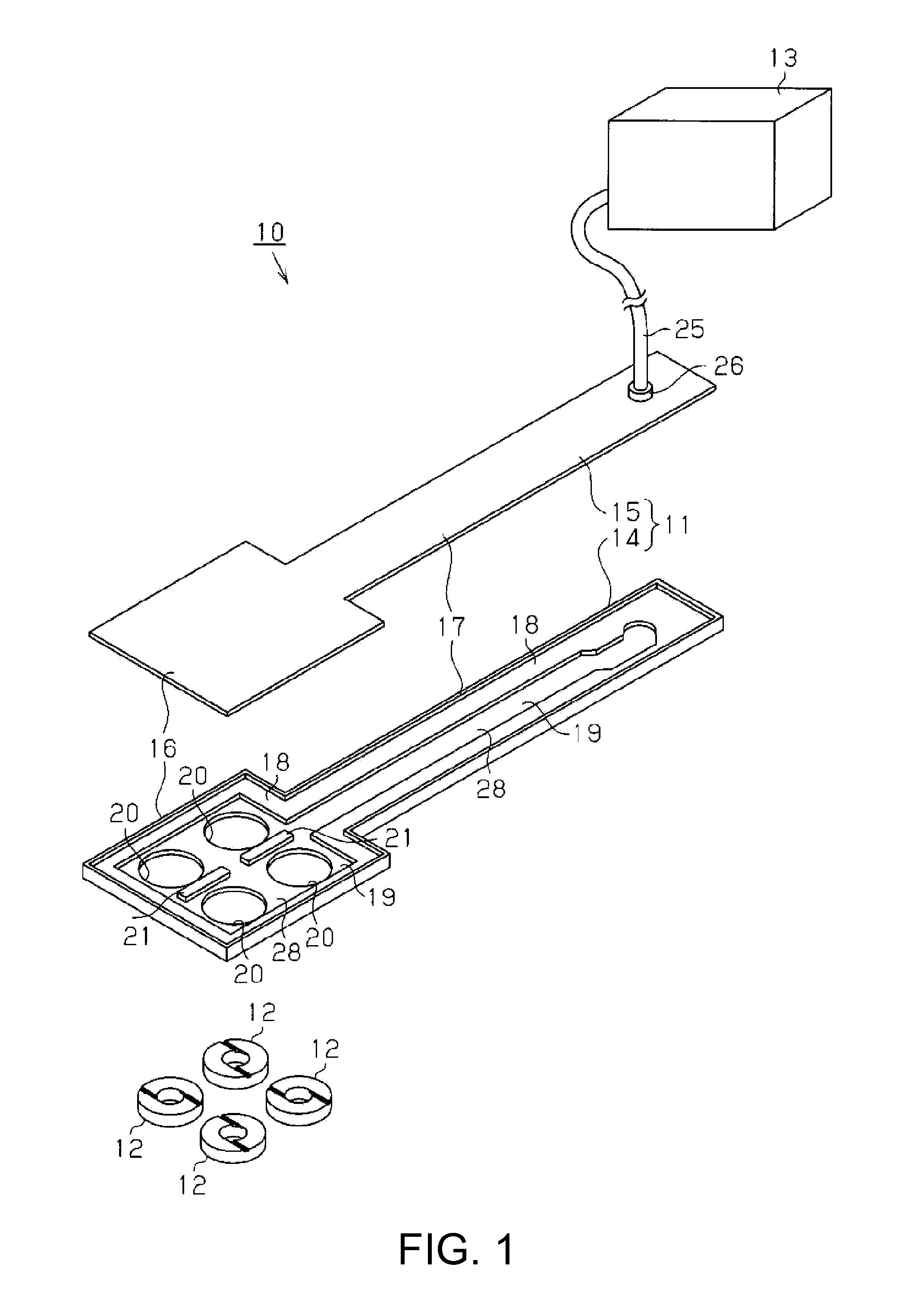
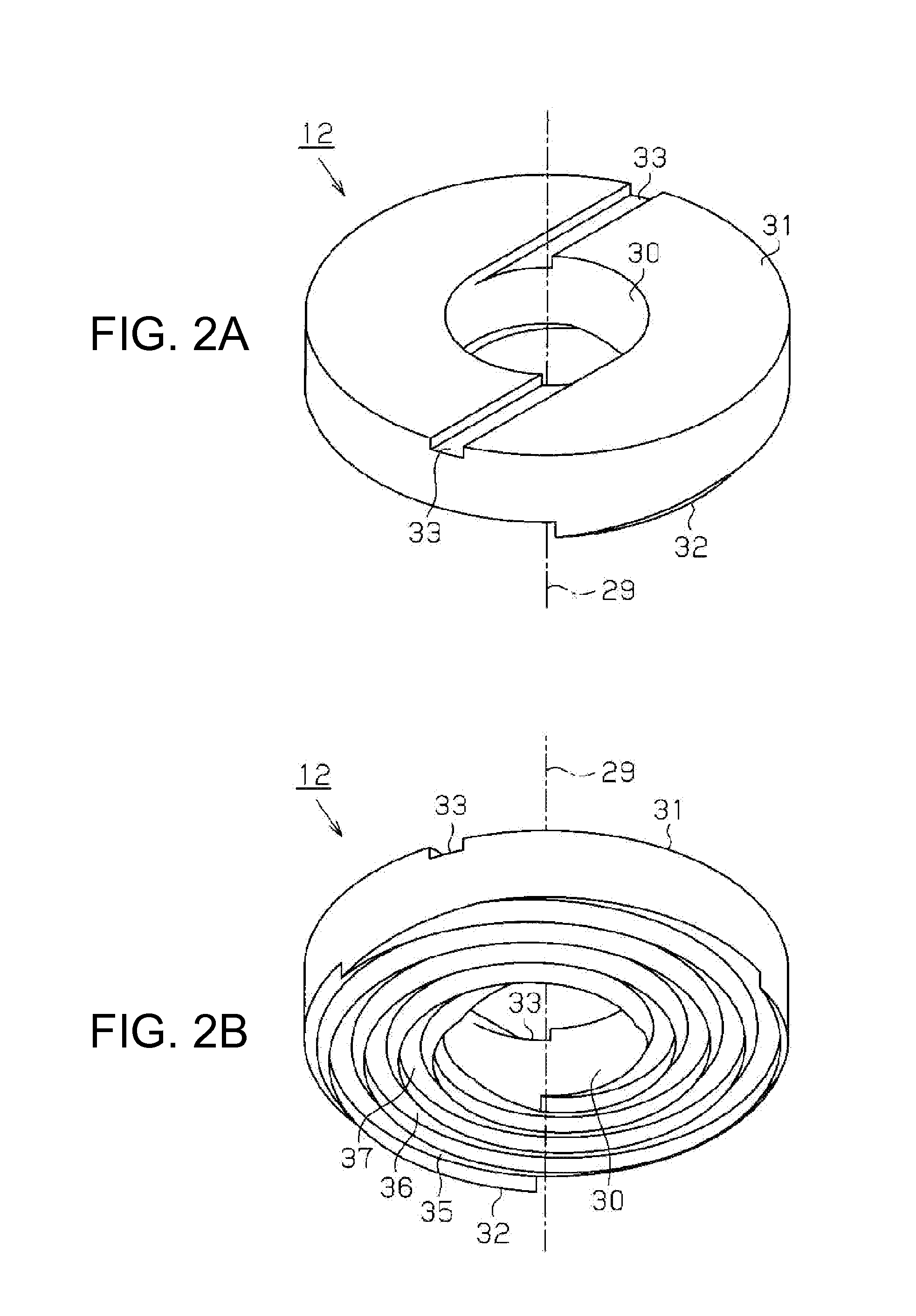
[0032]A non-contact holding hand including a non-contact holder according to an embodiment of the invention is hereinafter described with reference to FIGS. 1 through 38. FIG. 1 is a perspective view illustrating a disassembled non-contact holding hand. FIGS. 2A and 2B illustrate the structure of a holding unit, wherein: FIG. 2A is a perspective view of the holding unit as viewed from the side opposite to a holding surface; and FIG. 2B is a perspective view of the holding unit as viewed from the holding surface. FIG. 3A is a plan view of the holding unit as viewed from the holding surface, and FIG. 3B is a cross-sectional view taken along a line A-A in FIG. 3A.

[0033]As illustrated in FIG. 1, a non-contact holding hand 10 includes a case unit 11, holding units 12 as column bodies, and a compressed air supply source 13 as a gas supply source.

[0034]The case unit 11 is constituted by a lower case 14 and an upper case 15 fixed to the lower case 14. The case unit 11 has a holder portion 1...


PUM


Abstract

A non-contact holder holds the workpiece on the holding surface without contact between the workpiece and the holding surface by generating a negative pressure at the opening using a circular flow of gas introduced into the inside of the column body and generating a positive pressure between the holding surface and the workpiece using the gas flowing from the opening provided on the holding surface, and the holding surface has (2n+1) (n: a positive integer) guide grooves which have spiral shapes extending in spiral directions in correspondence with the circulation direction of the circular flow and have starting ends communicating with the opening to guide the gas introduced through the starting ends in the spiral directions, the final ends of the guide grooves being disposed at equal intervals on the circumference of the holding surface around the opening.

Description

CROSS-REFERENCE TO RELATED APPLICATIONS[0001]This application claims priority to Japanese Patent Application No. 2009-297054 filed on Dec. 28, 2009. The entire disclosure of Japanese Patent Application No. 2009-297054 is hereby incorporated herein by reference.BACKGROUND[0002]1. Technical Field[0003]The present invention relates to a non-contact holder and a non-contact holding hand capable of holding a holding target without contact between the holding target and a holding surface of the non-contact holder or the non-contact holding hand by using a negative pressure and a positive pressure acting on different areas of the holding target.[0004]2. Related Art[0005]A non-contact holder which holds a workpiece such as a liquid crystal substrate and a semiconductor wafer without contact between the workpiece and a holding surface of the non-contact holder is known as disclosed in JP-A-2008-87910, for example. A typical non-contact holder which uses a circular flow of gas is constituted ...

Claims


Application Information

Patent Timeline
Patent Type & Authority Applications(United States)
IPC IPC(8): B25B11/00
CPCB25B11/007
Inventor HARADA, KENICHIMORIYA, TOMONORI
Owner SEIKO EPSON CORP
Why Eureka
Try Eureka