
Recharging or connection tray for portable electronic devices

Inactive Publication Date: 2011-06-30
TOYODA GOSEI CO LTD
View PDF49 Cites 43 Cited by
  • Summary
  • Abstract
  • Description
  • Claims
  • Application Information

AI Technical Summary

Benefits of technology

[0008]The tray and assembly of the invention allows the charging and / or connection of a portable electronic system in or to a host, such as a vehicle, without the need for unique cords. The tray allows a user to view the display of one or more portable electronic devices in a convenient and safe manner. The tray and assembly of the invention allow the user to utilize portable electronic devices in a safer manner.

Problems solved by technology

In many locations, such as a vehicle, the presence of the cords is unsightly and may cause safety problems, because the cords can interfere with the function of other devices or controls of the host.
The problems presented to the user of portable electronic devices in a host system, such as a vehicle, are many.
One problem is the need to recharge portable electronic devices using unique cords for each device.
Another problem is that such devices have unique direct connection systems which prevent the use of a universal connection system in a host system.
Another problem is the need for one or more cords which can be strung in inconvenient places or can present safety problems due to their location, for instance in or around vehicle shift controls or other vehicle controls.
Another problem associated with the use of portable electronic devices is the need for the user to view one or more displays associated with the portable electronic devices and the lack of a place for locating the portable electronic devices to facilitate easy viewing of the displays, for instance in a vehicle.

Method used


Image

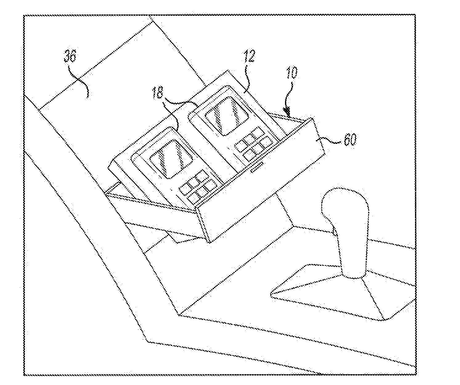
  • Recharging or connection tray for portable electronic devices
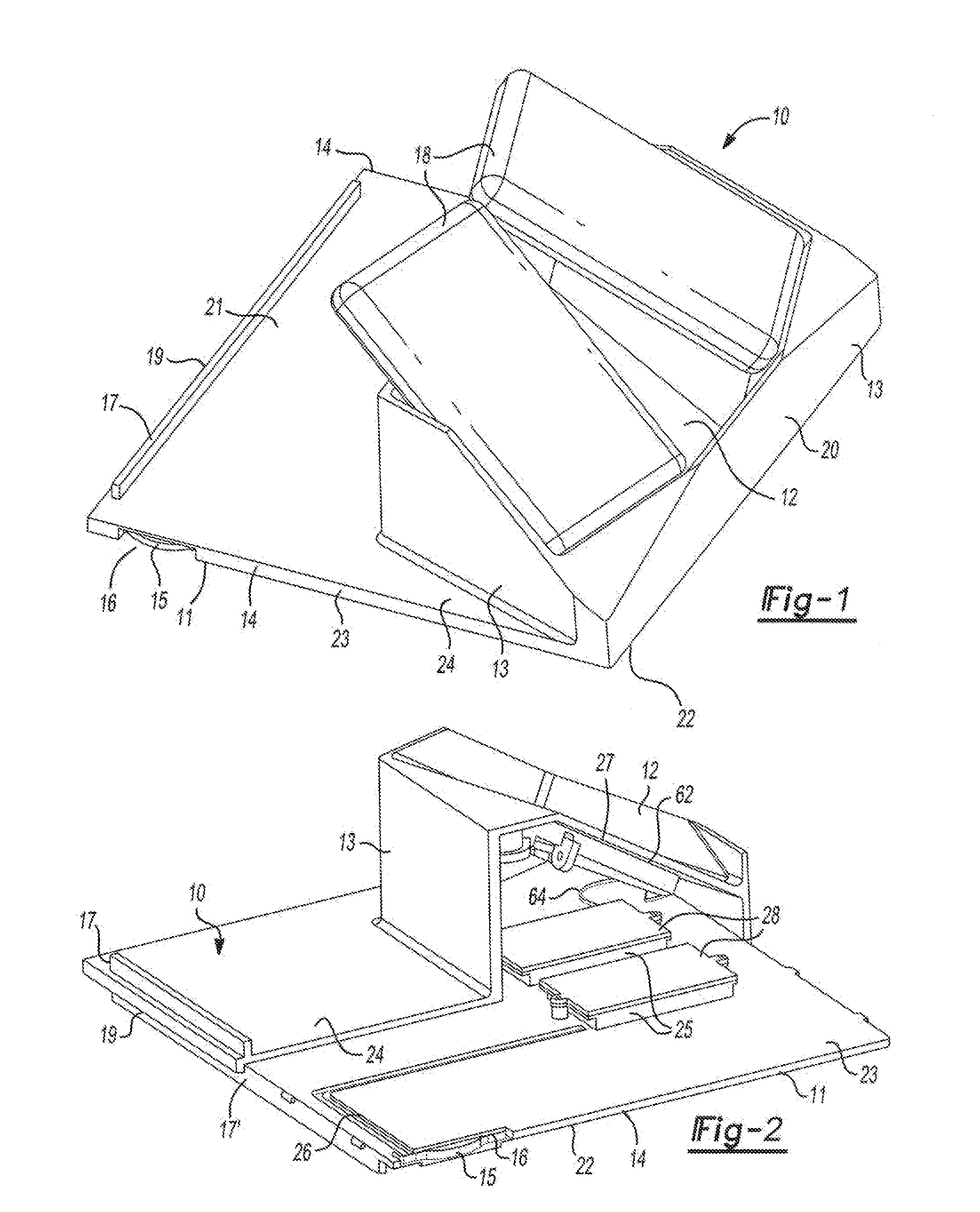
  • Recharging or connection tray for portable electronic devices
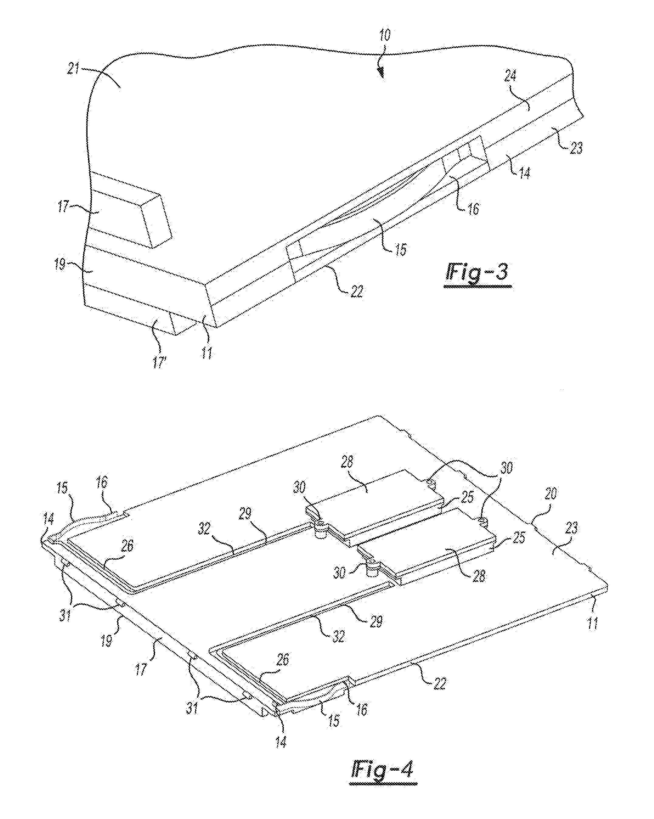
  • Recharging or connection tray for portable electronic devices

Examples


Embodiment Construction

[0018]The invention relates to trays useful in recharging and connecting portable electronic devices to a host. Host as used herein means any system wherein a portable electronic device can be used or interacts to share information, including those locations where the trays and assemblies of the invention can be utilized in conjunction with a portable electronic device. Such hosts can be a vehicle or a system which uses or generates information, such as an entertainment system or a computer system. Preferably the host is a vehicle.

[0019]In one embodiment, the invention is a tray which is adapted to perform one or more of the following functions: recharge a portable electronic device either wirelessly or through a dedicated connection; store a portable electronic device; support the portable electronic device in a manner such that a display on the device is easily visible to a user; secure the portable electronic device in a desired location; eliminate the need for one or more chargi...


PUM

PropertyMeasurementUnit
Energyaaaaaaaaaa
Electromagnetic fieldaaaaaaaaaa

Abstract

The present invention relates to a tray comprising: a) a base panel having two opposite edges adapted for sliding within grooves of a structure; b) a pair of electrical contacts located on the two opposite edges of the base adapted to conduct electricity; c) a battery recharging system adapted to provide one or more electromagnetic fields capable of transferring an electrical charge to a properly equipped electrical device having a rechargeable battery or a connection for a portable electronic device adapted to connect the portable electronic device to the power system of a host and / or other electronic systems of the host; d) means for connecting the pair of electrical contacts to the battery recharging system or to the connection to the portable electronic device; e) one or more display panels providing a surface for resting one or more rechargeable portable electric devices upon, such panels adapted to allow one or more users of portable electronic device to view one or more displays of the portable electronic devices; f) panels for connecting the base panel and one or more display panels and for enclosing the tray. The tray is adapted for use in a host system which supplies power to the tray. In a preferred embodiment, the host system is or is utilized in a vehicle.

Description

CROSS REFERENCE TO RELATED APPLICATIONS[0001]This application claims priority from U.S. Provisional Application Ser. No. 61 / 290,348 filed Dec. 28, 2009 titled “Movable Magnet and Panel Assembly”; from U.S. Provisional Application Ser. No. 61 / 290,352 filed Dec. 28, 2009 titled “Recharging or Connection Tray For Portable Electronic Devices” and from U.S. Provisional Application Ser. No. 61 / 326,893 filed Apr. 22, 2010 titled “Recharging or Connection Tray For Portable Electronic Devices”, all incorporated herein by reference.FIELD OF THE INVENTION[0002]The present invention relates generally to a recharging or connection tray for portable electronic devices and to assemblies containing such trays. The trays and assemblies are especially useful in vehicles.BACKGROUND OF THE INVENTION[0003]Portable electronic devices are common place and many people carry one or more. Portable electronic devices require recharging and often need to be placed in communication with another, system which us...

Claims


Application Information

Patent Timeline
IPC IPC(8): H02J7/00
CPCB60N3/002B60R11/02B60R2011/0005B60R2011/0007B60R2011/0075Y10T29/49826H02J7/0021H02J7/0027H02J7/0044H02J7/025B60N2002/0264B60R2011/0094H02J50/70H02J7/0013H02J50/90H02J50/40H02J50/10B60N2/0264
Inventor THORSELL, ROYMILLER, THOMAS A.
Owner TOYODA GOSEI CO LTD
Learn More