Apparatus and techniques for decelerated ion beam with no energy contamination

a technology of ion beam and beamline, applied in the field of beamline ion implanters, can solve the problems of energy contamination, energy contamination, and inability to transport for long, and achieve the effects of avoiding energy contamination, avoiding energy contamination, and avoiding energy contamination

Active Publication Date: 2018-12-04
VARIAN SEMICON EQUIP ASSOC INC
View PDF23 Cites 0 Cited by
  • Summary
  • Abstract
  • Description
  • Claims
  • Application Information

AI Technical Summary

Benefits of technology

[0031]There are multiple advantages provided by the present embodiments. A first advantage involves the ability to reduce the energy contamination in medium energy and low energy ion implanters without redesign of the accelerator columns. The present embodiments provide the additional advantage of a convenient and safe manner to reduce energy contamination from energetic neutrals.

Problems solved by technology

Such low energy high current beams will not transport for long distances in a beamline because of space charge forces that cause the ions to repel one another.
In known ion implanters, the architecture with deceleration near the wafer introduces a risk of energy contamination from energetic species that strike the substrate.
While neutrals traveling in a straight direction may fail to reach the substrate, energy contamination is found even in ion implanters having a bend in a deceleration stage.

Method used


Image

  • Apparatus and techniques for decelerated ion beam with no energy contamination
  • Apparatus and techniques for decelerated ion beam with no energy contamination
  • Apparatus and techniques for decelerated ion beam with no energy contamination

Examples


Embodiment Construction

[0014]The present embodiments will now be described more fully hereinafter with reference to the accompanying drawings, where some embodiments are shown. The subject matter of the present disclosure may be embodied in many different forms and are not to be construed as limited to the embodiments set forth herein. These embodiments are provided so this disclosure will be thorough and complete, and will fully convey the scope of the subject matter to those skilled in the art. In the drawings, like numbers refer to like elements throughout.

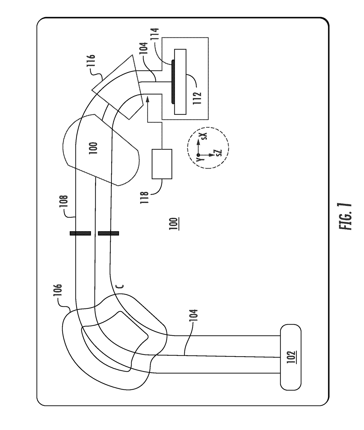
[0015]The present embodiments are related to ion beam processing apparatus such as beamline implanters. Various embodiments may be useful in beamline ion implanters where ion energy may range up to approximately 500 keV, and in particular embodiments ion energy may be below 50 keV. The embodiments are not limited in this context. As detailed below, the present embodiments facilitate operation of ion implanters at relatively lower energy, such as belo...


PUM


Abstract

An ion implantation system may include an ion source to generate an ion beam, a substrate stage disposed downstream of the ion source; and a deceleration stage including a component to deflect the ion beam, where the deceleration stage is disposed between the ion source and substrate stage. The ion implantation system may further include a hydrogen source to provide hydrogen gas to the deceleration stage, wherein energetic neutrals generated from the ion beam are not scattered to the substrate stage.

Description

FIELD[0001]The present embodiments relate to beamline ion implanters and more particularly to electrodes in ion implanters for accelerating an ion beam.BACKGROUND[0002]In the present day, beamline ion implanters employ multiple components to direct an ion beam from an ion source to a substrate. In order to properly treat a substrate, the ion beam may be accelerated or decelerated to a target ion energy, and may have the trajectory and shape of the ion beam manipulated by various beamline components to produce a set of target characteristics of the ion beam at the substrate. In many types of ion implanters, including medium energy and low energy ion implanters, an ion source may generate an ion beam that is guided down a beamline at a relatively high energy, while decelerated to a final energy just before impacting a substrate. This procedure is used because a best way to produce high current beams (having current more than ≈1 mA) at low energy (under ≈10 keV) is to transport an ion ...

Claims


Application Information

Patent Timeline
Patent Type & Authority Patents(United States)
IPC IPC(8): H01L21/265H01J37/20H01J37/08H01J37/317G21K5/10
CPCH01J37/3171H01J37/08H01J37/20H01J2237/0475H01J2237/006H01J2237/0206H01J37/3002H01J37/04H01J2237/0042H01J2237/022H01J2237/04756H01J37/3007
Inventor SINCLAIR, FRANKTIEGER, DANIELBECKER, KLAUS
Owner VARIAN SEMICON EQUIP ASSOC INC
Why Eureka
Try Eureka