Light source apparatus, exposure apparatus and device fabrication method

Inactive Publication Date: 2007-02-01
CANON KK
View PDF3 Cites 43 Cited by
  • Summary
  • Abstract
  • Description
  • Claims
  • Application Information

AI Technical Summary

Benefits of technology

[0006] Accordingly, the present invention is directed to a light source apparatus t

Problems solved by technology

Moreover, a light intensity on a target surface to be illuminated becomes non-uniformly according to an adhes

Method used


Image

  • Light source apparatus, exposure apparatus and device fabrication method
  • Light source apparatus, exposure apparatus and device fabrication method
  • Light source apparatus, exposure apparatus and device fabrication method

Examples


Embodiment Construction

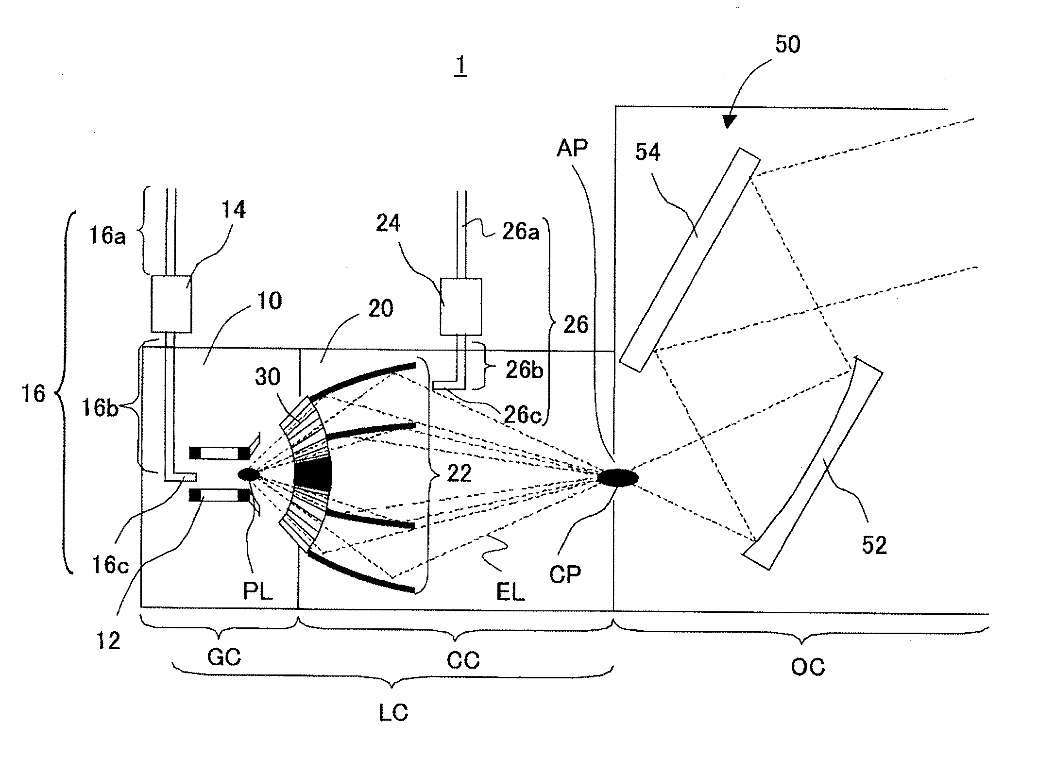
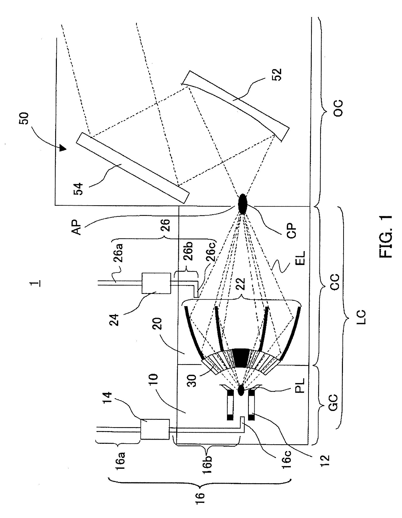
[0018] With reference to the accompanying drawings, a description will be given of a light source apparatus of one aspect according to the present invention. In each figure, the same reference numeral denotes the same element. Therefore, duplicate descriptions will be omitted. Here, FIG. 1 is a schematic sectional view of a light source apparatus 1 of the present invention.

[0019] The light source apparatus 1 is a light source apparatus that generates a plasma PL and supplies an EUV light EL irradiated from the plasma PL (a light with a wavelength of 20 nm or less, preferably, a light with a wavelength of 13 nm or more and 15 nm or less) to a subsequent optical system 50. The light source apparatus 1 is, in the instant embodiment, a discharge plasma light source. However, the light source apparatus 1 is not limited to the discharge plasma light source and may be a laser plasma light source or a light source of other method.

[0020] The light source apparatus 1 includes an electrode 1...


PUM


Abstract

A light source apparatus for generating a plasma and supplying a light irradiated from the plasma to an optical system, said light source apparatus includes a chamber for accommodating a region that generates the plasma, wherein a density of a hydrocarbon compound included in a gas in the chamber is 300 ppb or less.

Description

BACKGROUND OF THE INVENTION [0001] The present invention relates generally to an exposure apparatus, and more particularly to a light source apparatus used in an exposure apparatus for exposing an plate, such as a single crystal substrate of a semiconductor wafer etc. and a glass plate for a liquid crystal display (“LCD”). The present invention is suitable, for example, for an exposure apparatus that uses an extreme ultraviolet (“EUV”) light as a light source for exposure. [0002] A reduction projection optical system using an EUV light as an exposure light (referred to as an “EUV exposure apparatus” hereinafter) has been developed to manufacture a fine semiconductor device that has very fine circuit pattern of 0.1 μm or less. The EUV light is a light with a wavelength of 10 nm to 15 nm shorter than that of an ultraviolet light. [0003] The EUV exposure apparatus typically uses a laser plasma light source and a discharge plasma light source as the light source. See, for example, Japan...

Claims


Application Information

Patent Timeline
IPC IPC(8): G01J3/10
CPCB82Y10/00G03F7/70033G03F7/70916H05G2/005H05G2/003H05G2/006G03F7/70983
Inventor KANAZAWA, HAJIMEWATANABE, YUTAKAITO, JUNFUJIMOTO, KAZUKI
Owner CANON KK
Why Eureka
Try Eureka