Spin coated media

a technology of spin coated media and spherical fiber, applied in the field of spin coated media, to achieve the effect of uniform thickness, improved knitting, and reduced viscosity

Inactive Publication Date: 2002-10-24
SABIC INNOVATIVE PLASTICS IP BV
View PDF99 Cites 41 Cited by
  • Summary
  • Abstract
  • Description
  • Claims
  • Application Information

AI Technical Summary

Benefits of technology

0023] Employment of spin coating to attain a substantially uniform thickness (e.g., a thickness deviation of less than or equal to 10%, with a thickness deviation of less than or equal to about 5% preferred), can be achieved through the use of a coating solution having a viscosity that attains a better knitting between the initial dispense solution and the last of the dispense solution (e.g., where the beginning and the end of the dispense ring meet to form the ring). Coating solution viscosities of less than or equal to about 2,000 centipoise (cps) can be employed, with less than or equal to about 750 cps preferred, and less than or equal to about 500 cps even more preferred. The lower the viscosity, the more the material tends to spread uniformly and produce a less pronounced knit line prior to spin-off.
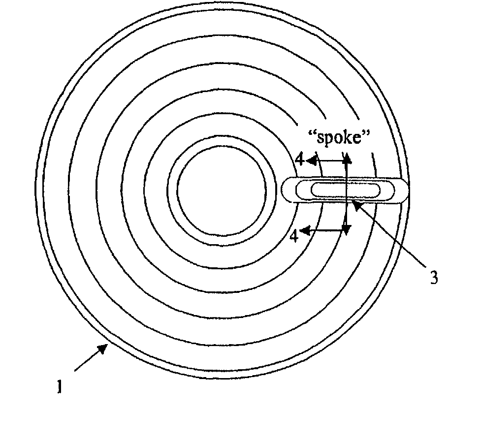
0024] Alone, or in addition to employing a reduced viscosity coating solution, the desired thickness uniformity can be obtained by employing a dynamic dispense methodology that produces a more uniform solution ring at or near the inner diameter of the substrate. One dispense pattern which can achieve substantial thickness uniformity comprises dispensing the solution while translating the dispense arm from the outer diameter to the inner diameter of the area to be coated while the disk is spinning. (See FIG. 6) Preferably, once the inner diameter to be coated is reached, the arm is held over that area for at least one full revolution, whereupon the arm is retranslated back to the outer diameter of the substrate and the solution dispense is ended. This method results in a spiral of solution across the surface of the disk and a uniform ring of solution at the inner diameter. Since the abrupt start and stoppage of coating solution is not performed at the inner diameter of the area to be coated, imperfections in the inner ring from this are avoided, and thickness uniformity is attained (e.g., thickness deviations of down to and below about 5%).
0025] Alternatively, the d

Problems solved by technology

Due to the very low tolerances between the read/write device and the storage media, the quality of the layers, e.g., sur

Method used


Image

  • Spin coated media
  • Spin coated media
  • Spin coated media

Examples


example 1

[0056] A plastic coating that was spin coated on to a glass substrate was formed having a R.sub.a of about 4 .ANG. asperities numbered less than 10 having a height of greater than 25 nm; a microwaviness of about 25 nm over a 4 mm.sup.a area; a thickness uniformity of .+-.10% of the nominal thickness. A coating solution of 18 wt % Ultem.RTM. 1000 (based upon the total weight of the solution) in 50:50 anisole(polarity index of 3.8):acetophenone (polarity index of 4.8) solution was filtered to a nominal particle size of 0.05 .mu.m. The filtered solution having a viscosity of about 1,200 centipoise was dynamically dispensed on the substrate in a spiral fashion while the substrate was spinning at a rate of 150 rpm on the chuck shown in FIG. 8. The coating was then spun at 3,500 rpm for 35 seconds. The coated substrate was then annealed at 300.degree. C. for 2 hours (about 85.degree. C. over the Ultem.RTM. glass transition temperature (T.sub.g) of 217.degree. C.).

example 2

[0057] A plastic coating that was spin coated onto a glass substrate was formed having a R.sub.a of about 4 .ANG. a microwaviness of about 25 nm over a 4 mm.sup.2 area; a thickness uniformity of .+-.10% nominal thickness. A coating solution of 16 wt % oxydianhydride / metaphenylenediam-ine polyamic acid (based upon the total weight of the solution) in 40:60 anisole:NMP (N-methylpyrrolidone; polarity index of 6.7) solution filtered to a nominal particle size of 0.2 .mu.m. The filtered solution having a viscosity of 360 centipoise was dynamically dispensed on the substrate in a spiral fashion while the substrate was spinning at a rate of 150 rpm on the chuck shown in FIG. 8. The filtered solution was dynamically dispensed on the substrate in an arc fashion while the coating was then spun at 3,500 rpm for 35 seconds. The coated substrate was then annealed at 350.degree. C. for 1 hour (about 50.degree. C. over the polyetherimide T.sub.g of about 300.degree. C).

example 3

[0058] A plastic coating that was spincoated onto a glass substrate was formed having a R.sub.a of about 5 .ANG. a microwaviness of about 25 nm over a 4 mm.sup.2 area; a thickness uniformity of .+-.10% nominal thickness. A coating solution of 18 wt % Ultem 1000 (based upon the total weight of the solution) in 50:50 anisole:gammabutyrolactone solution was filtered to a nominal particle size of 0.2 .mu.m. The filtered solution having a viscosity of 1,200 centipoise was dynamically dispensed on the substrate in a spiral fashion while the substrate was spinning at a rate of 150 rpm on the chuck shown in FIG. 8. The coating was then spun at 3,500 rpm for 35 seconds. The coated substrate was then annealed at 300.degree. C. for 2 hours (about 85.degree. C. over the Ultem.RTM. T.sub.g).

[0059] By employing the chuck design, solvent blend, dispensing techniques, thermal annealing, and / or filtering, plastic coated substrates that meet stringent surface quality requirements are readily produced...


PUM

PropertyMeasurementUnit
Temperatureaaaaaaaaaa
Lengthaaaaaaaaaa

Abstract

In one embodiment, a spin coating process comprises: dispensing a solution of a solution solvent and about 3 to about 30 wt % thermoplastic polymer, based upon the total weight of the solution, wherein the solution solvent has a boiling point at atmospheric pressure of about 110° C. to about 250° C., a polarity index of greater than or equal to about 4.0, a pH of about 5.5 to about 9; spinning the substrate; and removing the solution solvent to produce a coated substrate comprising a coating having less than or equal to 10 asperities over the entire surface of the coated substrate.

Description

[0001] This application claims the benefit of the filing date of U.S. Provisional Application Serial No. 60 / 285,088 filed Apr. 19, 2001, Attorney Docket Nos. GP2-0207 and RD-29180; No. 60 / 285,022 filed Apr. 19, 2001, Attorney Docket Nos. GP2-0208 and RD-29126 / RD-29160; and No. 60 / 285,014 filed Apr. 19, 2001, Attorney Docket Nos. GP2-0209 and RD-28242 / RD-29113; the entire contents of each application are hereby incorporated by reference.BACKGROUND OF INVENTION[0002] Optical, magnetic and magneto-optic media are primary sources of high performance storage technology that enable high storage capacity coupled with a reasonable price per megabyte of storage. Areal density, typically expressed as billions of bits per square inch of disk surface area (Gbits per square inch (Gbits / in.sup.2)), is equivalent to the linear density (bits of information per inch of track) multiplied by the track density in tracks per inch. Improved areal density has been one of the key factors in the price reduc...

Claims


Application Information

Patent Timeline
IPC IPC(8): B05D1/40B05D1/00B05D1/26C03C17/32G11B5/738G11B5/84G11B7/24G11B7/258G11B7/26G11B11/105
CPCB05D1/005G11B11/10582C03C2218/116G11B5/84G11B7/24G11B7/2433G11B7/2472G11B7/248G11B7/252G11B7/2531G11B7/2532G11B7/2542G11B7/2548G11B7/256G11B7/2578G11B7/258G11B7/266C03C17/32G11B7/26
Inventor REITZ, JOHN BRADFORDCHENG, MINQUANDIETZ, ALBERT G. IIIFEIST, THOMAS P.GALLUCCI, ROBERT R.GORCZYCA, THOMAS B.
Owner SABIC INNOVATIVE PLASTICS IP BV
Why Eureka
Try Eureka