Dry-type sand making method and dry-type sand making machine thereof

A kind of sand making machine and dry technology, which is applied in the direction of grain processing, etc., can solve the problems of difficult control of dusty airflow overflow, the surrounding environment and equipment, production personnel are greatly affected, and the operating cost is increased, so as to achieve good dust removal effect, The effect of improving the production environment and improving the crushing efficiency

Inactive Publication Date: 2009-02-11
吴核明
View PDF1 Cites 48 Cited by
  • Summary
  • Abstract
  • Description
  • Claims
  • Application Information

AI Technical Summary

Problems solved by technology

[0002] In the current artificial sand making process, vertical shaft impact crushers are generally used for wet production; this process has the advantages of good sand quality and high production efficiency, but this process requires a lot of water, and thus brings a lot of The treatment of sediment wastewater is difficult and seriously pollutes the environment
Due to the use of water in the sand making process, the production efficiency is also reduced, and the on-site calculation efficiency can be reduced by more than 40%; and due to the existence of water, the equipment is easy to rust, which leads to increased wear and shortened service life of parts
In the subsequent process steps of this kind of wet production, a large amount of water cleaning is required to remove dust; this not only brings about the loss of small-sized sand particles (according to statistics, the loss ratio of this part is about 10%), As a result, the consumption of raw materials has been increased, and there are still a large number of waste disposal problems after sand washing
[0003] If the dry method is simply used to produce artificial sand, the dust pollution will be very serious, which will have a great impact on the surrounding environment, equipment and production personnel, and cannot be applied to actual production at all.
[0004] The environmental-friendly powder-selecting sand-making machine with the patent number 03239994.4 proposes a dry-type sand-making scheme, which eliminates the influence of dust by closing it, and uses the fan on the main shaft to drive the internal airflow to blow and separate the dust; its structure is due to the fan In equipment with heavy particles of large and small sand and dust, and the wear of the equipment during operation is very serious, resulting in an increase in wearing parts and an increase in operating costs
At the same time, the fan and the rotor of the crusher run coaxially, and there is mutual restraint between the two, which makes it difficult to debug the process parameters, and it is difficult to achieve the best effect of crushing and separation.
And because of the internal blowing method, the dust-laden gas is in a positive pressure state, which is prone to leakage, making it difficult to control the overflow of dust-laden air
And after adopting the simple dust removal process described in this plan, the gas emission is still difficult to meet the requirements of environmental protection

Method used


Image

  • Dry-type sand making method and dry-type sand making machine thereof
  • Dry-type sand making method and dry-type sand making machine thereof

Examples


Embodiment 1

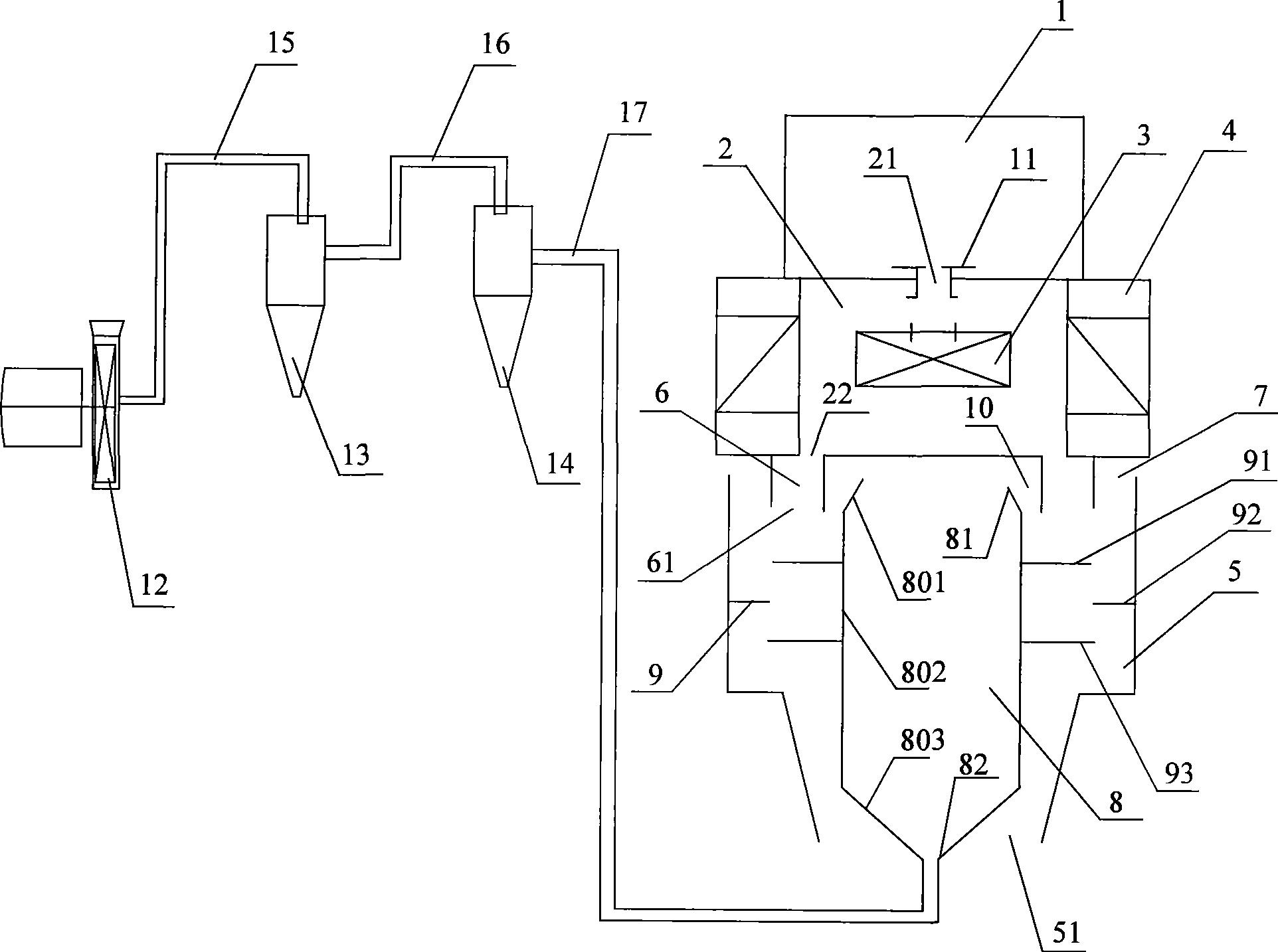
[0023] Embodiment 1, figure 1 A dry sand making machine is provided, which includes a barrel-shaped hollow crushing working chamber 2, and the center of the upper surface of the crushing working chamber 2 is provided with a circular through hole as the feed port 21; The mouth 21 is provided with a gate adjusting device 11, and the gate adjusting device 11 is used to adjust the opening size of the feeding port 21. Above the crushing working chamber 2 is provided a feed bin 1 which communicates with a feed port 21 . An annular through hole is provided on the lower surface of the crushing working chamber 2 as the feeding port 22 ; the center of the circular through hole overlaps with the central axis of the crushing working chamber 2 . A rotor 3 is provided in the crushing working chamber 1, and the rotor 3 is driven by a motor located outside the crushing working chamber 1 through a transmission shaft (this is the prior art, for clarity of the drawing, the corresponding motor a...

Embodiment 2

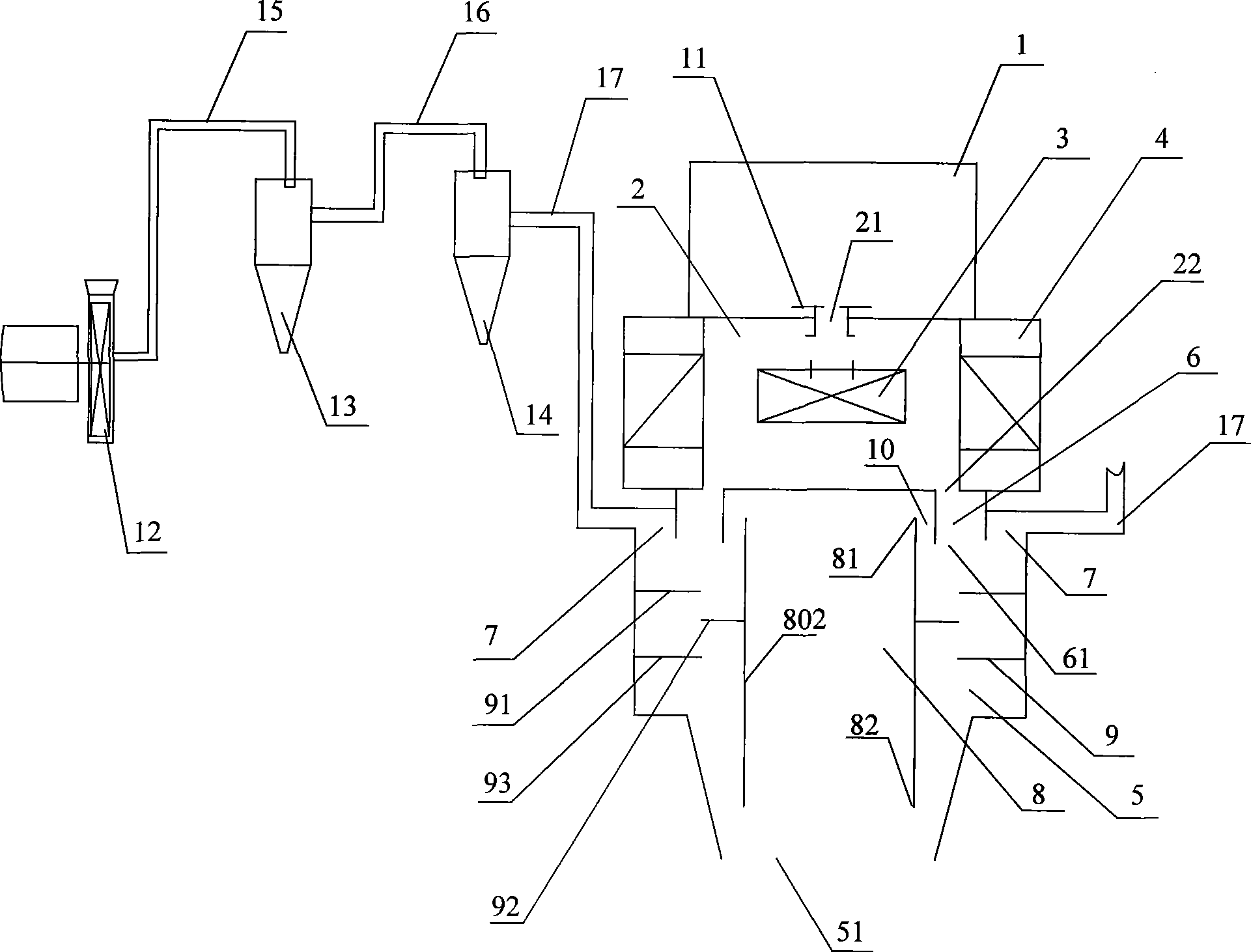
[0045] Embodiment 2, figure 2 Another dry sand making machine is given, the air duct 8 is only formed by a topless and bottomless cylindrical shape 802 (that is, the upper neck 801 and the lower neck 803 in Embodiment 1 are canceled), at this time The gap between the outer surface of the air duct 8 (i.e. the outer surface of the cylinder 802) and the inner ring surface of the feeding channel 6 forms a pipeline settlement zone 10; this pipeline settlement zone 10 is a circular ring with uniform thickness up and down. body. The other end of the pipeline III17 is canceled to be connected with the seal of the lower end 82 of the air duct 8, and changed into: the other end of the pipeline III17 is connected to the air vent 7 in a sealed manner. That is to say, the present embodiment 2 is to change the dust removal structure in the middle of the ventilation shown in the embodiment 1 into the dust removal structure of the ventilation around, and the rest of the structures are the s...


PUM


Abstract

The invention discloses a dry sand maker which comprises a hollow crushing cavity (2). A hollow dust removal cavity (5) is arranged under the hollow crushing cavity (2); the upper end of a feeding channel (6) is hermetically connected with a feeding mouth (22) and the lower end (61) thereof is positioned in the dust removal cavity (5) on which an air vent (7) is also arranged; an air duct (8) is arranged in the dust removal cavity (5); the lower end (61) of the feeding channel (6) is staggered with the upper end (81) of the air duct (8) in the horizontal direction; the bottom surface of the dust removal cavity (5) is provided with an outlet (51); a dust absorption component is hermetically connected with the lower end (82) of the air duct (8) or the air vent (7) after passing through the outlet (51). The invention also provides a method for drying sand making simultaneously. By adopting the dry sand maker, the drying sand making can have the advantages of high production efficiency and low environmental pollution.

Description

technical field [0001] The invention relates to a dry sand making method and a used dry sand making machine. Background technique [0002] In the current artificial sand making process, vertical shaft impact crushers are generally used for wet production; this process has the advantages of good sand quality and high production efficiency, but this process requires a lot of water, and thus brings a lot of The treatment of sediment waste water is difficult and seriously pollutes the environment. Due to the use of water in the sand making process, the production efficiency is also reduced, and the on-site calculation efficiency can be reduced by more than 40%; and due to the existence of water, the equipment is easy to rust, which leads to increased wear and shortened service life of parts . In the subsequent process steps of this kind of wet production, a large amount of water cleaning is required to remove dust; this not only brings about the loss of small-sized sand partic...

Claims


Application Information

Patent Timeline
Patent Type & Authority Applications(China)
IPC IPC(8): B02C19/00B02C23/02B02C23/30
Inventor 方国平
Owner 吴核明
Why Eureka
Try Eureka