Extractor hood

A technology of range hoods and cabinets, applied in the field of kitchen appliances, can solve the problems of short paths, inability to maximize the effect of rotating filter airflow, and large wind resistance, so as to achieve large negative pressure gradients, improve the effect of range hoods, The effect of improving smoking efficiency

Pending Publication Date: 2019-04-09
NINGBO FOTILE KITCHEN WARE CO LTD
View PDF5 Cites 2 Cited by
  • Summary
  • Abstract
  • Description
  • Claims
  • Application Information

AI Technical Summary

Problems solved by technology

Although this kind of smoker can realize direct suction and straight exhaust, similar to the above-mentioned vertical or inclined fan, the rotary filter can only be arranged at the air inlet of the centrifugal fan, and the motor of the centrifugal fan or a separate The motor is driven to rotate, which will not only cause a large wind resistance, but also the rotating filter screen will rectify the oil fume to a certain extent and then enter the centrifugal fan. The path is too short, and the effect of the rotating filter screen to make the air flow smooth cannot be reflected to the greatest extent.

Method used


Image

  • Extractor hood
  • Extractor hood
  • Extractor hood

Examples


Embodiment 1

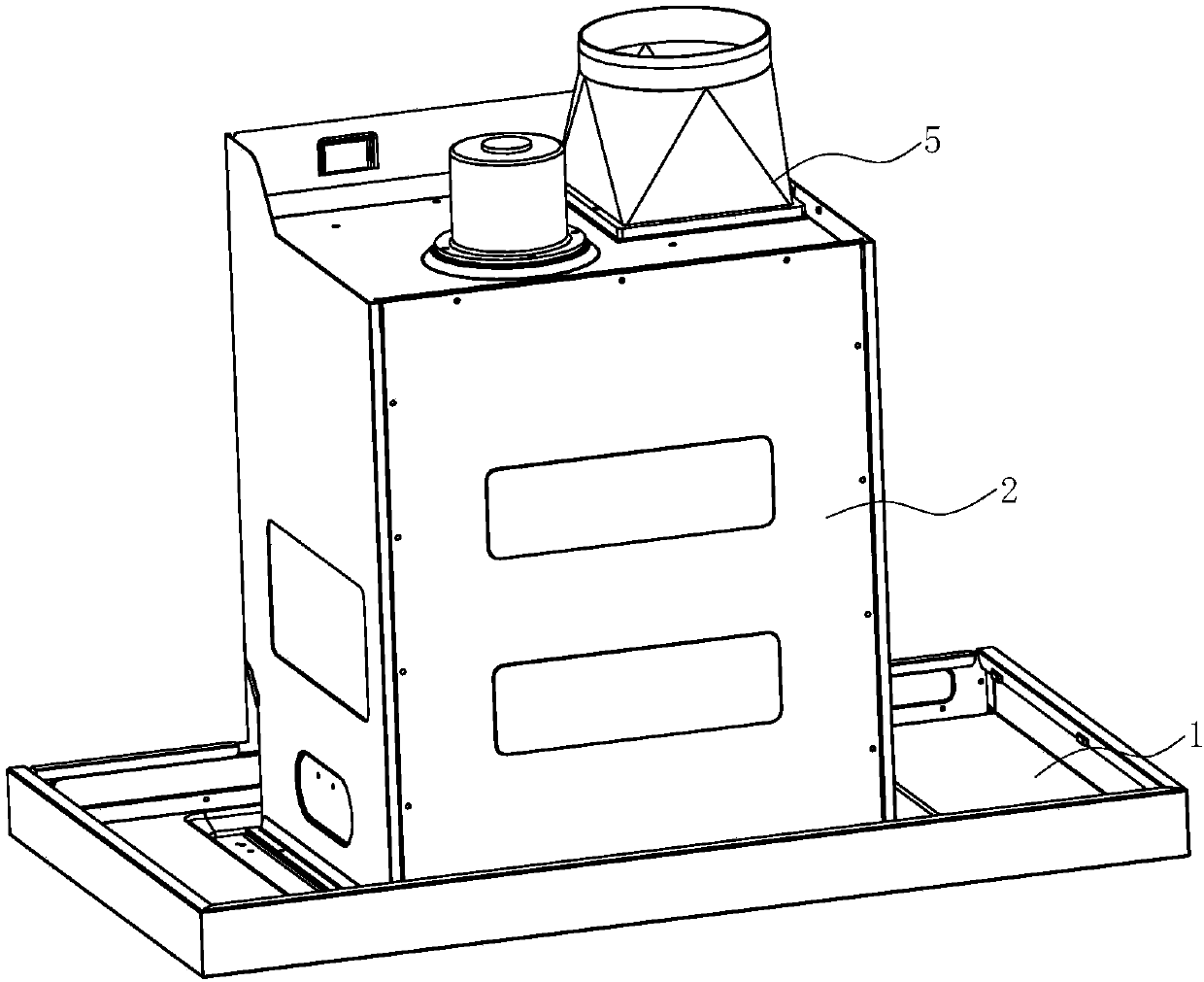
[0032] see Figure 1 ~ Figure 4 , a range hood, comprising a smoke collection hood 1, a chassis 2 arranged above the fume collection hood 1, a fan system 4 is arranged in the chassis 2. An air inlet 11 is provided on the fume collecting hood 1, so that the fan system 4 in the cabinet 2 can suck oily fume into the cabinet 2 through the air inlet 11 and discharge it to the public flue.

[0033] The cabinet 2 includes a left side wall 21, a right side wall 22, a front side wall 23, and a rear side wall 24. The cavity between the above-mentioned side walls forms an air duct 25 for the oil fume flow. Preferably, the air duct 25 gradually moves from bottom to top. zoom out.

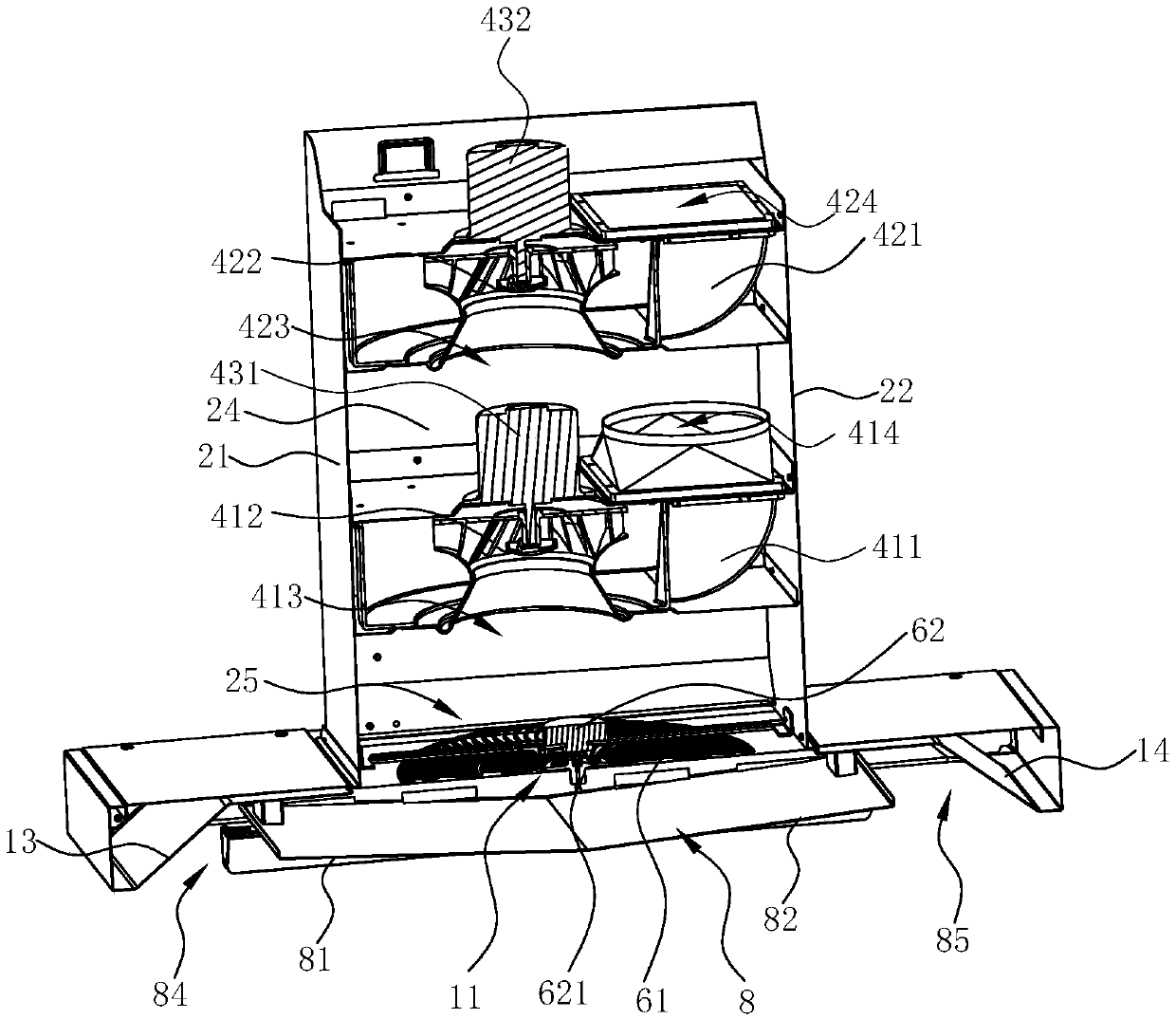
[0034] In this embodiment, the blower system 4 is a three-way blower, and the three-way blower can adopt the existing technology, as disclosed in the Chinese patent application number 201310418009.X. The fan system 4 can be a single ternary fan, two parallel ternary fans or two series ternary fans. Since the ...

Embodiment 2

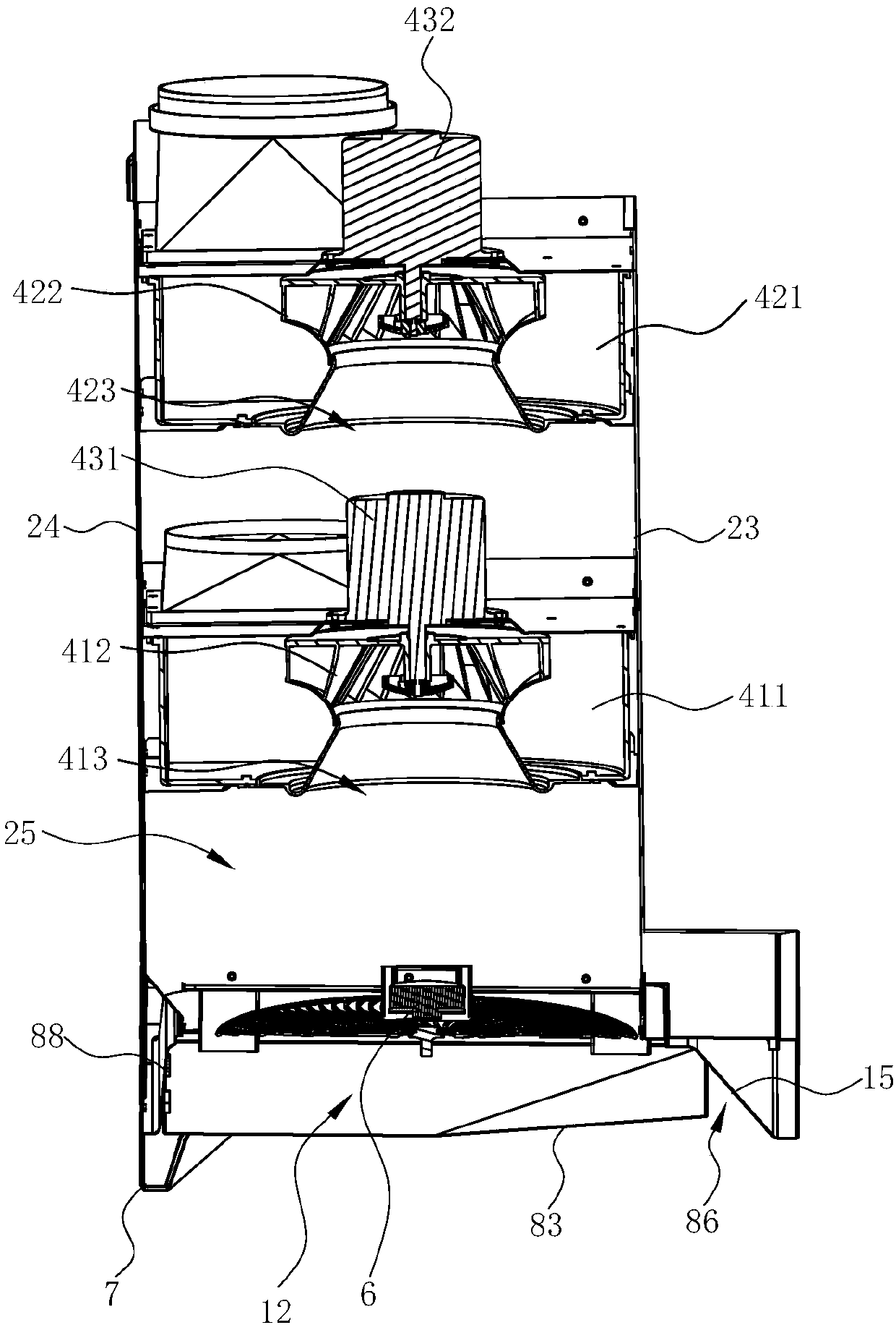
[0055] see Figure 7 with Figure 8 , in this embodiment, the difference from the third embodiment above is that the first ternary fan 41 (as the first-stage fan) and the second ternary fan 42 (as the second-stage fan) are arranged in a misplaced position, that is, the second The first volute 411 and the second volute 412 are opposite, the first air inlet 413 of the first three-way fan 41 is close to the right side, the second air inlet 423 of the second three-way fan 42 is close to the left side, and the first three-way fan 41 is close to the left side. The second air outlet 414 of fan 41 is close to the left side, and the second air outlet 424 of the second three-way fan 42 is close to the right side. The second air inlet 423 corresponds or nearly corresponds in the vertical direction. The distance between the first air inlet 413 and the second air inlet 423 is the distance in the vertical direction.

Embodiment 3

[0057] see Figure 9 with Figure 10 , in this embodiment, the difference from the third embodiment above is that the first three-way fan 41 and the second three-way fan 42 are arranged at intervals above and below, respectively, that is, the first inlet of the first three-way fan 41 The air outlet 413 faces downward obliquely with the horizontal direction, and the second air inlet 423 of the second three-way blower 42 faces downward obliquely with the horizontal direction.

[0058] The first air outlet 414 of the first three-way fan 41 is connected to the second air inlet 423 of the second three-way fan 42 through an air duct 46 . The vertical distance between the center of the first air inlet 413 of the first three-way fan 41 and the inlet of the air duct 25 is 0.5-2 times the diameter of the first three-way impeller 412 .

[0059] This kind of oblique series connection method makes the overall height of the fans lower and the static pressure at the fan outlet is larger, w...


PUM


Abstract

The invention discloses an extractor hood. The extractor hood comprises a fume collecting hood, a machine case arranged above the fume collecting hood, and a draught fan system arranged in the machinecase. The fume collecting hood is provided with an air inlet, a fume guiding plate is arranged below the air inlet, and the draught fan system comprises a first ternary draught fan and a second ternary draught fan which are connected in series. At least one part of the lower surface of the fume guiding plate gradually inclines upwards from the middle to the edge and is matched with the corresponding wall face of the fume collecting hood accordingly so that an acceleration runner with the cross section gradually reduced from bottom to top can be defined. Through the acceleration runner, the volume of the cooking fume entering the extractor hood within the unit time can be increased, and the cooking fume suction effect is enhanced; and through a rotation filter net arranged at the positionof an air flue inlet, the cooking fume passes through the rotation filter net with the low flow speed before being accelerated by the air flue, the mutual contact time of the cooking fume and the rotation filter net is long, and sufficient collisions between the cooking fume and the rotation filter net can be achieved.

Description

technical field [0001] The invention relates to kitchen appliances, in particular to a range hood. Background technique [0002] Range hoods have become one of the indispensable kitchen appliances in modern families. Generally, range hoods include top-suction and near-suction types. Top-suction range hoods use the principle of rising hot air to absorb and discharge the naturally rising oil fumes generated during cooking. It has more and more widespread applications. [0003] Existing range hoods are equipped with filter screens for the purpose of collecting cooking fumes, dust, and the like. For example, a range hood disclosed in a Chinese patent with application number 200780027956.9 has a hood with an air duct, an exhaust fan located in the air duct, a filter screen located in the air duct and in front of the exhaust fan, and the driving part is connected to On the filter screen, a flat rectifying plate is arranged near the suction port in the hood; another example is a...

Claims


Application Information

Patent Timeline
Patent Type & Authority Applications(China)
IPC IPC(8): F24C15/20
CPCF24C15/20
Inventor 刘逸梁雪斐茅忠群诸永定刘戈
Owner NINGBO FOTILE KITCHEN WARE CO LTD
Why Eureka
Try Eureka