Range hood

A range hood and oil fume technology, which is applied in the field of kitchen appliances, can solve the problems of large wind resistance, the smooth airflow of the rotating filter screen cannot be fully reflected, and the short path, etc., to achieve a large negative pressure gradient, improve the effect of the range hood, small size effect

Pending Publication Date: 2019-04-09
NINGBO FOTILE KITCHEN WARE CO LTD
View PDF5 Cites 1 Cited by
  • Summary
  • Abstract
  • Description
  • Claims
  • Application Information

AI Technical Summary

Problems solved by technology

Although this kind of smoker can realize direct suction and straight exhaust, similar to the above-mentioned vertical or inclined fan, the rotary filter can only be arranged at the air inlet of the centrifugal fan, and the motor of the centrifugal fan or a separate The motor is driven to rotate, which will not only cause a large wind resistance, but also the rotating filter screen will rectify the oil fume to a certain extent and then enter the centrifugal fan. The path is too short, and the effect of the rotating filter screen to make the air flow smooth cannot be reflected to the greatest extent.

Method used


Image

  • Range hood
  • Range hood
  • Range hood

Examples


Embodiment 1

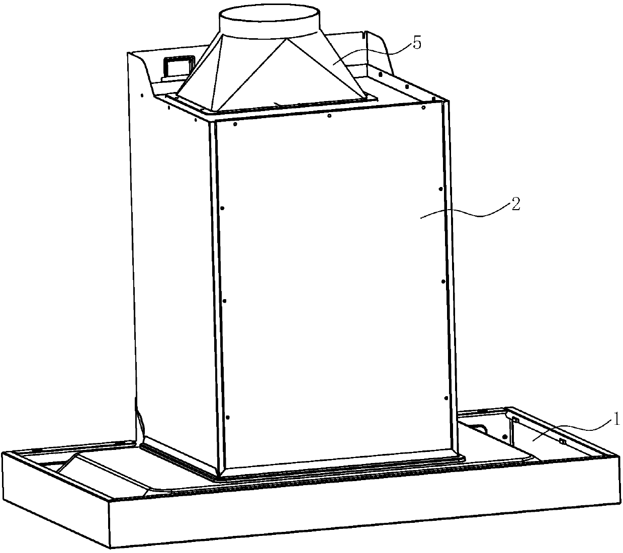
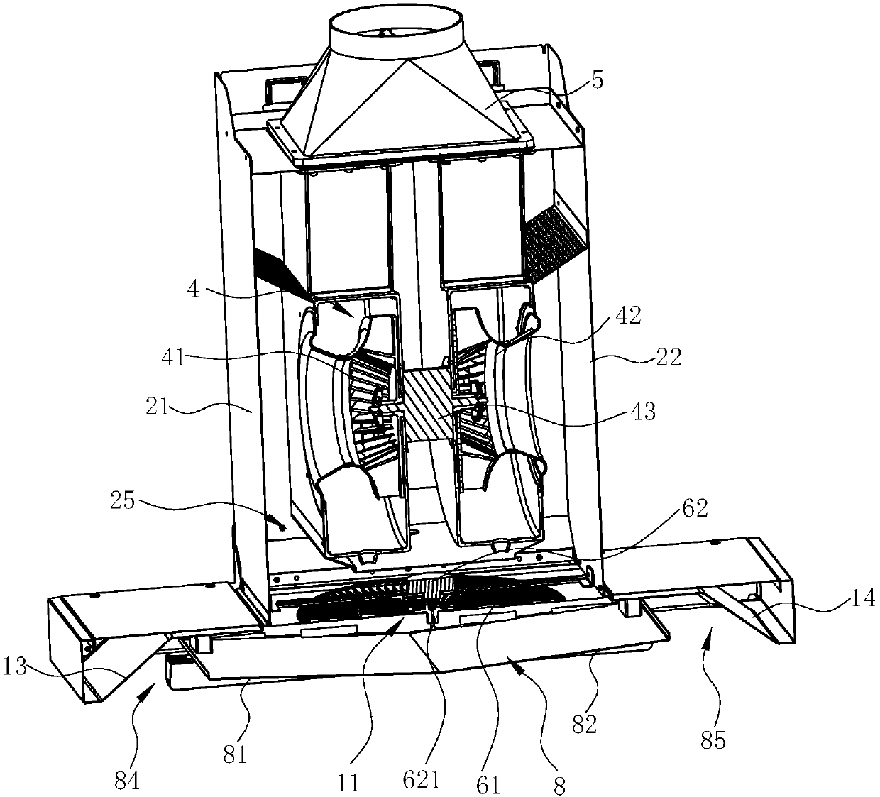
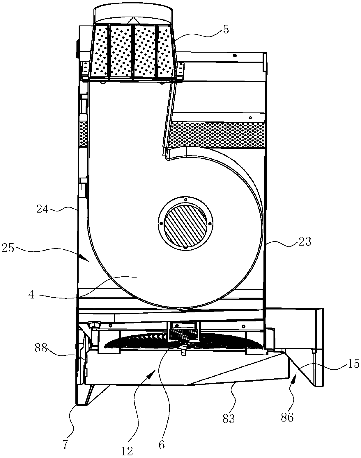
[0034] see Figure 1 ~ Figure 4, a range hood, comprising a smoke collection hood 1, a chassis 2 arranged above the fume collection hood 1, a fan system 4 is arranged in the chassis 2. An air inlet 11 is provided on the fume collecting hood 1, so that the fan system 4 in the cabinet 2 can suck oily fume into the cabinet 2 through the air inlet 11 and discharge it to the public flue.

[0035] The cabinet 2 includes a left side wall 21, a right side wall 22, a front side wall 23, and a rear side wall 24. The cavity between the above-mentioned side walls forms an air duct 25 for the oil fume flow. Preferably, the air duct 25 gradually moves from bottom to top. zoom out.

[0036] In this embodiment, the blower system 4 is a three-way blower, and the three-way blower can adopt the existing technology, as disclosed in the Chinese patent application number 201310418009.X. The fan system 4 can be a single ternary fan, two parallel ternary fans or two series ternary fans. Since the t...

Embodiment 2

[0060] see Figure 9 and Figure 10 , in this embodiment, the difference from the first embodiment above is that the first ternary fan system 41 and the second ternary fan system 42 share the same volute 44, that is, the first ternary fan system 41 of the first ternary fan system 41 The first three-way impeller 412 and the second three-way impeller 422 of the second three-way blower system 42 are both arranged in the same volute 44 .

[0061] A mounting plate 45 is arranged between the two ternary impellers, thereby separating the two ternary impellers on both sides of the mounting plate 45, and the mounting plate 45 extends to the top of the volute 44, thereby dividing the volute 44 into two The first oil fume passage 441 and the second oil fume passage 442 are independent. The driving motor 43 passes through the mounting plate 45 and is connected and fixed with the mounting plate 45 .

[0062] In this embodiment, the air outlet cover 5 only includes a cover body 51 and a ...


PUM


Abstract

The invention discloses a range hood. The range hood comprises a smoke collecting hood, a cabinet arranged above the smoke collecting hood and a fan system arranged in the cabinet. An air inlet is formed in the smoke collecting hood. A smoke guide plate is arranged below the air inlet. The fan system comprises a first three-element fan and a second three-element fan which are arranged in parallel.At least a part of the lower surface of the smoke guide plate is gradually inclined upwards from the middle to the edge so as to be matched with the corresponding wall surface of the smoke collectinghood to define an acceleration flow channel with the cross section which is gradually reduced from bottom to top. The amount of oil smoke entering the range hood in unit time can be increased throughthe acceleration flow channel, so that the oil smoke suction effect is improved. A rotary filter screen is arranged at an inlet of an air duct, so that the oil smoke can pass through the rotary filter screen at a lower flow rate before being accelerated by the air flue, the contact time is long, and the oil smoke can fully collide with the rotary filter screen.

Description

technical field [0001] The invention relates to kitchen appliances, in particular to a range hood. Background technique [0002] Range hoods have become one of the indispensable kitchen appliances in modern families. Generally, range hoods include top-suction and near-suction types. Top-suction range hoods use the principle of rising hot air to absorb and discharge the naturally rising oil fumes generated during cooking. It has more and more widespread applications. [0003] Existing range hoods are equipped with filter screens for the purpose of collecting cooking fumes, dust, and the like. For example, a range hood disclosed in a Chinese patent with application number 200780027956.9 has a hood with an air duct, an exhaust fan located in the air duct, a filter screen located in the air duct and in front of the exhaust fan, and the driving part is connected to On the filter screen, a flat rectifying plate is arranged near the suction port in the hood; another example is a...

Claims


Application Information

Patent Timeline
Patent Type & Authority Applications(China)
IPC IPC(8): F24C15/20
CPCF24C15/2035
Inventor 梁雪斐周佳杰王艳辉董一龙茅忠群诸永定刘戈
Owner NINGBO FOTILE KITCHEN WARE CO LTD
Why Eureka
Try Eureka