
Cooling fan

A heat dissipation fan and resistor technology, applied in the direction of non-variable pumps, electrical components, control systems, etc., can solve the problems of fan blade rotation speed limitation, achieve stable speed, good heat dissipation effect, and low power

Inactive Publication Date: 2014-02-26
SHENZHEN LIANXIANG MOTOR
View PDF6 Cites 1 Cited by
  • Summary
  • Abstract
  • Description
  • Claims
  • Application Information

AI Technical Summary

Problems solved by technology

[0003] However, since this cooling fan uses alternating current, the change of the alternating magnetic field depends on the frequency of the alternating current, and the rotation of the rotor depends on the change of the alternating magnetic field, which limits the rotation speed of the fan blades.

Method used


Image

  • Cooling fan
  • Cooling fan
  • Cooling fan

Examples


Embodiment Construction

[0018] In order to make the purpose, technical solutions and advantages of the embodiments of the present invention clearer, the technical solutions in the embodiments of the present invention will be clearly and completely described below in conjunction with the drawings in the embodiments of the present invention. Obviously, the described embodiments It is a part of embodiments of the present invention, but not all embodiments. Based on the embodiments of the present invention, all other embodiments obtained by persons of ordinary skill in the art without making creative efforts belong to the protection scope of the present invention.

[0019] The present invention will be described in further detail below through specific implementation examples and in conjunction with the accompanying drawings.

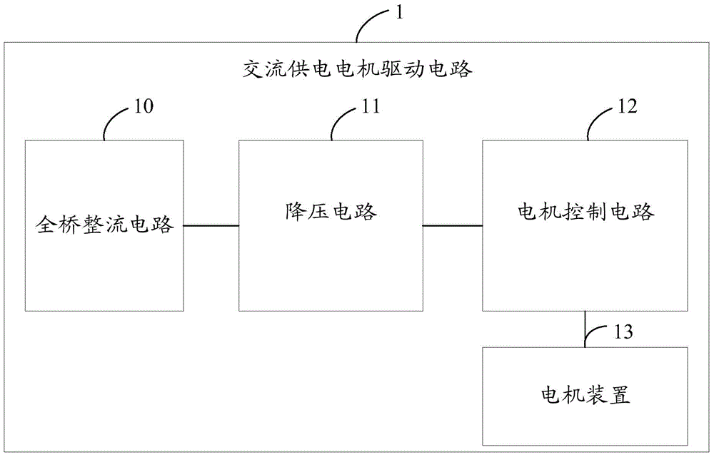
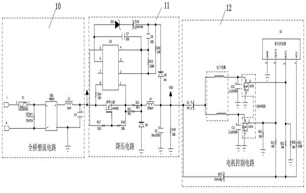
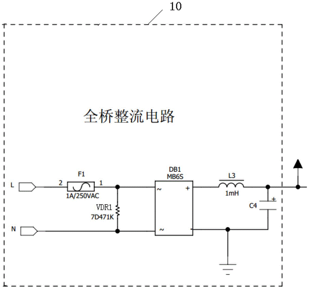
[0020] see figure 1 and figure 2 , a cooling fan, comprising: an AC power supply motor drive circuit 1, the AC power supply motor drive circuit 1 also includes a full-bridge re...


PUM


Abstract

The invention discloses a cooling fan which comprises an alternating current power supply motor driving circuit, wherein the alternating current power supply motor driving circuit also comprises a full-bridge rectifier circuit, a step-down circuit, a motor control circuit, a motor device and fan blade main bodies which are sequentially connected in series; the full-bridge rectifier circuit comprises a rectifier; the motor control circuit is electrically connected with the motor device; the motor device comprises a stator, a plurality of coils and a motor shell (an iron shell and magnetic stripes); the fan blade main bodies are fixedly connected with the motor shell; the coils are annularly arranged on the stator and is positioned in the motor shell of fan blades. The cooling fan is simple in circuit structure, and has the characteristics of high and stable rotating speed, good cooling effects, low power, high efficiency, energy conservation, high practicability and the like, and can be applied to the input voltage in a wide range, a wide alternating current input voltage range of 110 to 240V, and the direct current output voltage is 24V all the time.

Description

technical field [0001] The invention relates to the field of household appliances, in particular to a cooling fan. Background technique [0002] The existing cooling fan includes a stator and a rotor. The stator is supplied with alternating current, thereby forming an alternating magnetic field near the stator. The rotor is placed in the alternating magnetic field and is driven to rotate by the alternating magnetic field. In the process, it rotates with the rotation of the rotor. In this way, the AC magnetic field is generated by the alternating current, and the AC magnetic field is converted into the mechanical energy of the rotor. The mechanical energy of the rotor is converted into the kinetic energy of the fan blade, and the drive of the fan blade is completed. [0003] However, since this cooling fan uses alternating current, the change of the alternating magnetic field depends on the frequency of the alternating current, and the rotation of the rotor depends on the cha...

Claims


Application Information

Patent Timeline
Patent Type & Authority Applications(China)
IPC IPC(8): H02P27/00F04D25/08
Inventor 关洪敏
Owner SHENZHEN LIANXIANG MOTOR
Learn More