Camera system and camera control method

a camera system and control method technology, applied in the field of camera systems and camera control methods, can solve the problems of increasing the system configuration, increasing the operation load, complicated 3d camera systems, etc., and achieves the effects of extending the distance between the camera and the camera system, saving the engineer the load of taking images, and simplifying the configuration of the camera system

Active Publication Date: 2011-06-30
SONY CORP
View PDF13 Cites 9 Cited by
  • Summary
  • Abstract
  • Description
  • Claims
  • Application Information

AI Technical Summary

Benefits of technology

[0022]According to the present invention, a first control value is outputted to a first camera and, at the same time, a second control value with a difference corrected is outputted to a second camera in order to operate two units of cameras. Therefore, an engineer can control the two units of cameras as if the two units of cameras were one unit of camera. This novel configuration facilitates the configuration of the camera system, thereby saving the engineer the load of taking images for 3D imaging. In doing so, the two units of cameras output images that is homogenous to each other because the differences between these images are corrected.
[0023]At this time, the two units of cameras output images that are homogenous to each other because the

Problems solved by technology

This not only requires engineers of the high technical operation skills in executing image adjustment, but also makes the 3D cam

Method used


Image

  • Camera system and camera control method
  • Camera system and camera control method
  • Camera system and camera control method

Examples


Embodiment Construction

[0043]This invention will be described in further detail by way of embodiments thereof with reference to the accompanying drawings. The description will be made in the following order.

1. One embodiment of the invention (a camera control function; namely, an example in which two or more camera heads are used for a 3D camera system)

2. Variations to the above-mentioned embodiment

[Exemplary Configuration of a 3D Camera System]

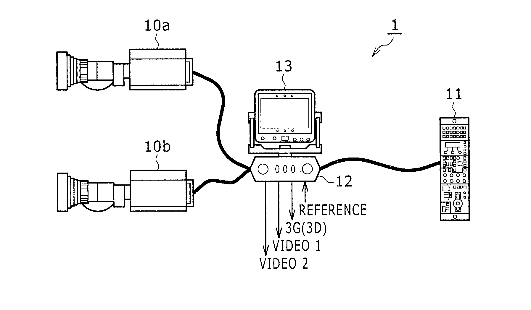
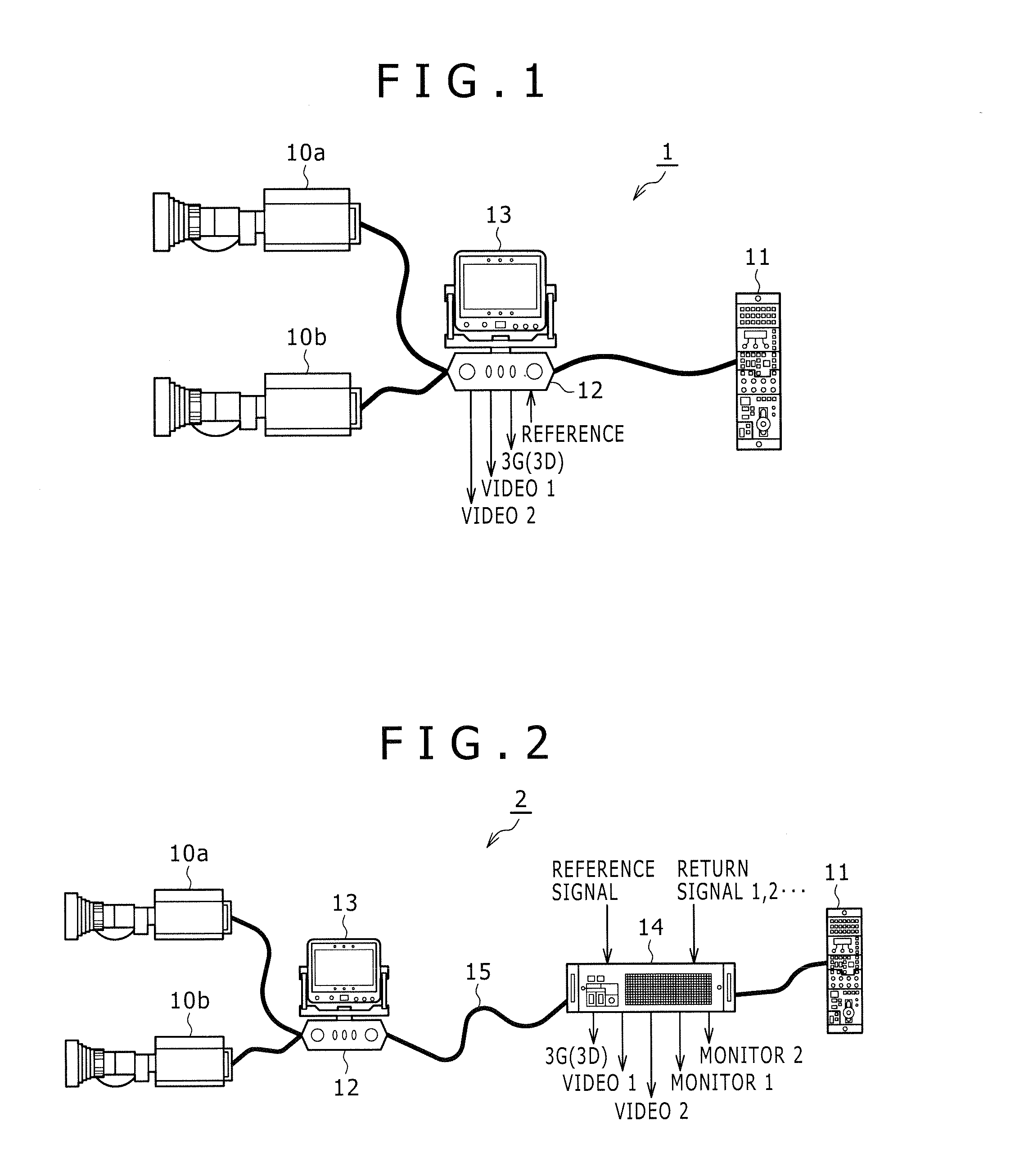
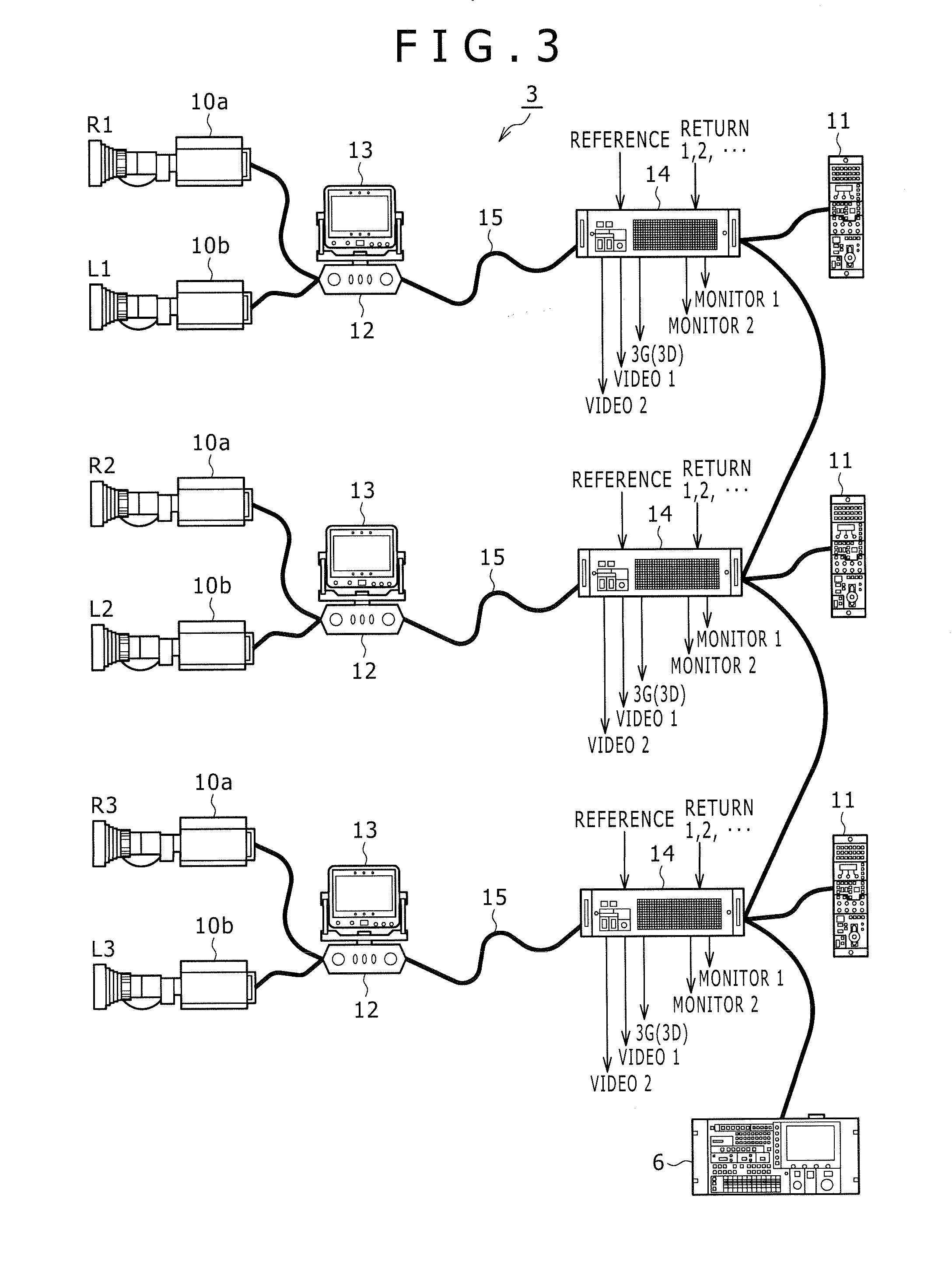
[0044]The following describes one embodiment of the present invention with reference to FIGS. 1 through 14. With one embodiment of the invention, examples of 3D camera systems each having a camera adaptor box 12 configured to output images taken by two camera heads 10a and 10b to an external apparatus by giving image taking instructions to these camera heads 10a and 10b.

[0045]Now, referring to FIG. 1, there is shown an exemplary configuration of a 3D camera system 1.

[0046]The 3D camera system 1 has an optical system, an image device, and so on, not shown, and has ...


PUM


Abstract

A camera system includes: a first camera and a second camera; a camera adaptor box; and a camera control unit.

Description

BACKGROUND OF THE INVENTION[0001]1. Field of the Invention[0002]The present invention relates to a camera system and a camera control method that are suitable for use in applications in which 3D (three dimensional) images are generated from the images taken by two units of cameras, for example.[0003]2. Description of the Related Art[0004]3D camera systems have been in use in which 3D images are obtained by combining the images separately taken by two different cameras.[0005]Referring to FIG. 15, there is shown an exemplary configuration of a related-art 3D camera system 101.[0006]The 3D camera system 101 has two cameras 110a and 110b, control panels 111a and 111b for controlling the operation of each of the cameras 110a and 110b, and a monitor 112 on which images outputted from the cameras 110a and 110b are displayed.[0007]A reference signal is directly entered in each of cameras 110a and 110b and each of the cameras 110a and 110b directly outputs a taken image to an external appara...

Claims


Application Information

Patent Timeline
IPC IPC(8): H04N13/02
CPCH04N5/232H04N13/0296H04N13/0239H04N13/239H04N13/296H04N23/631H04N23/69H04N2213/001
Inventor KAMIYA, KOJISATO, SEIJIKATSUYAMA, TOMOYASU
Owner SONY CORP
Why Eureka
Try Eureka