Radio communication system, radio communication method, and communication device

a radio communication system and communication device technology, applied in the field of radio communication system, radio communication method, communication device, can solve the problem of increasing transmission power in proportion to bandwidth

Inactive Publication Date: 2011-06-30
SHARP KK
View PDF5 Cites 18 Cited by
  • Summary
  • Abstract
  • Description
  • Claims
  • Application Information

AI Technical Summary

Benefits of technology

[0045]According to the present invention, the transmission device determines a mapping method for a downlink signal based on the reception device state information received from the reception device. Accordingly, the transmission device can transmit the downlink signal by the mapping method with which the reception device is compatible. Thus, the downlink signal having been subjected to a mapping suited to the BICM-ID can be transmitted to the reception device to which the BICM-ID is applied, and which is backward compatible with a reception device using the gray mapping.

Problems solved by technology

However, there is a problem in that the transmission power increases in proportion to the bandwidth.

Method used


Image

  • Radio communication system, radio communication method, and communication device
  • Radio communication system, radio communication method, and communication device
  • Radio communication system, radio communication method, and communication device

Examples


first embodiment

[0063]Hereinafter, a first embodiment of the present invention is explained in detail with reference to accompanying drawings.

[0064]A communication system according to the first embodiment of the present invention includes a reception device (second communication device) 200a and a transmission device (first communication device) 300. The reception device 200a and the transmission device 300 perform 16QAM modulation. The reception device 200a is compatible with the BICM-ID.

[0065]A transmission device 100 is included in, for example, a base station device in a cellular system. The reception device 200a is included in, for example, a mobile station device.

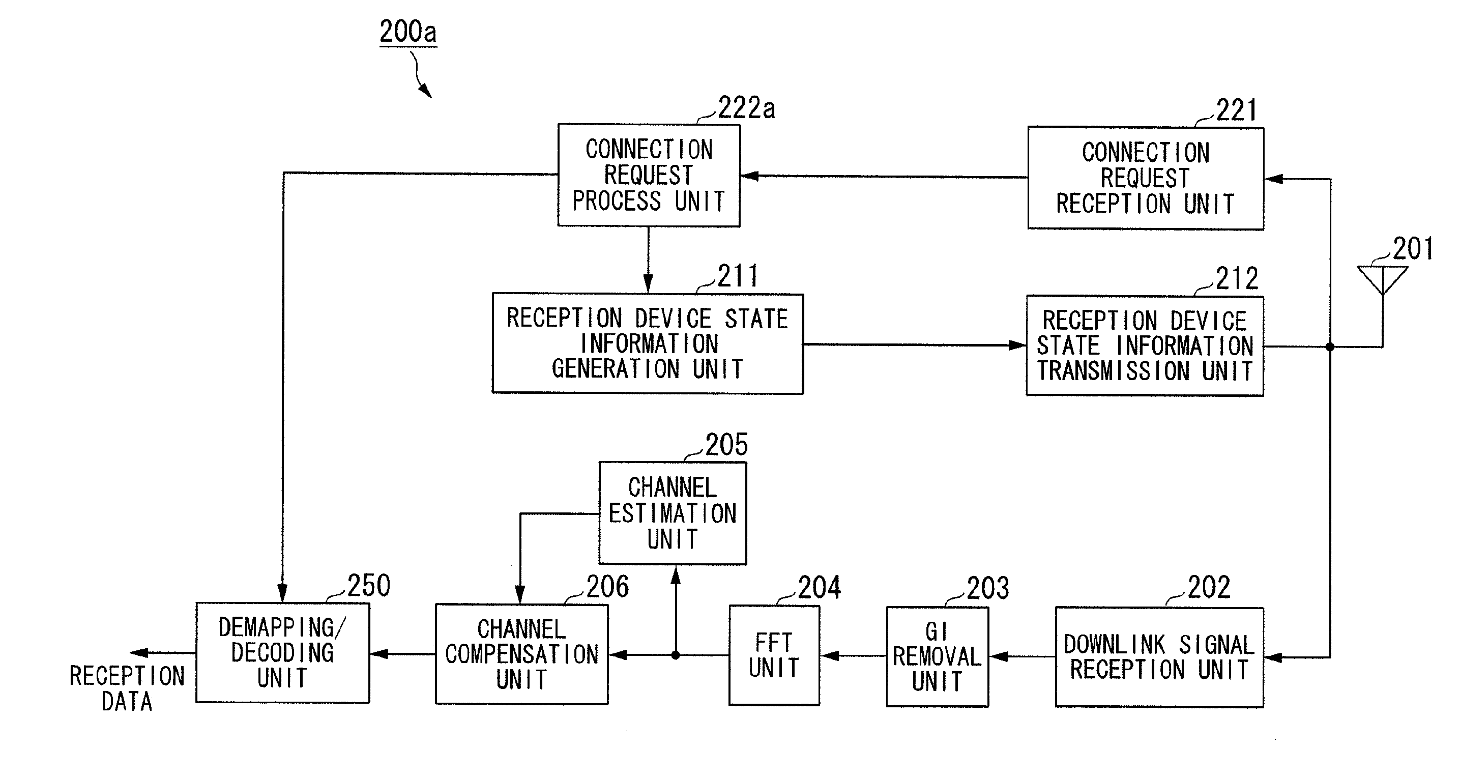
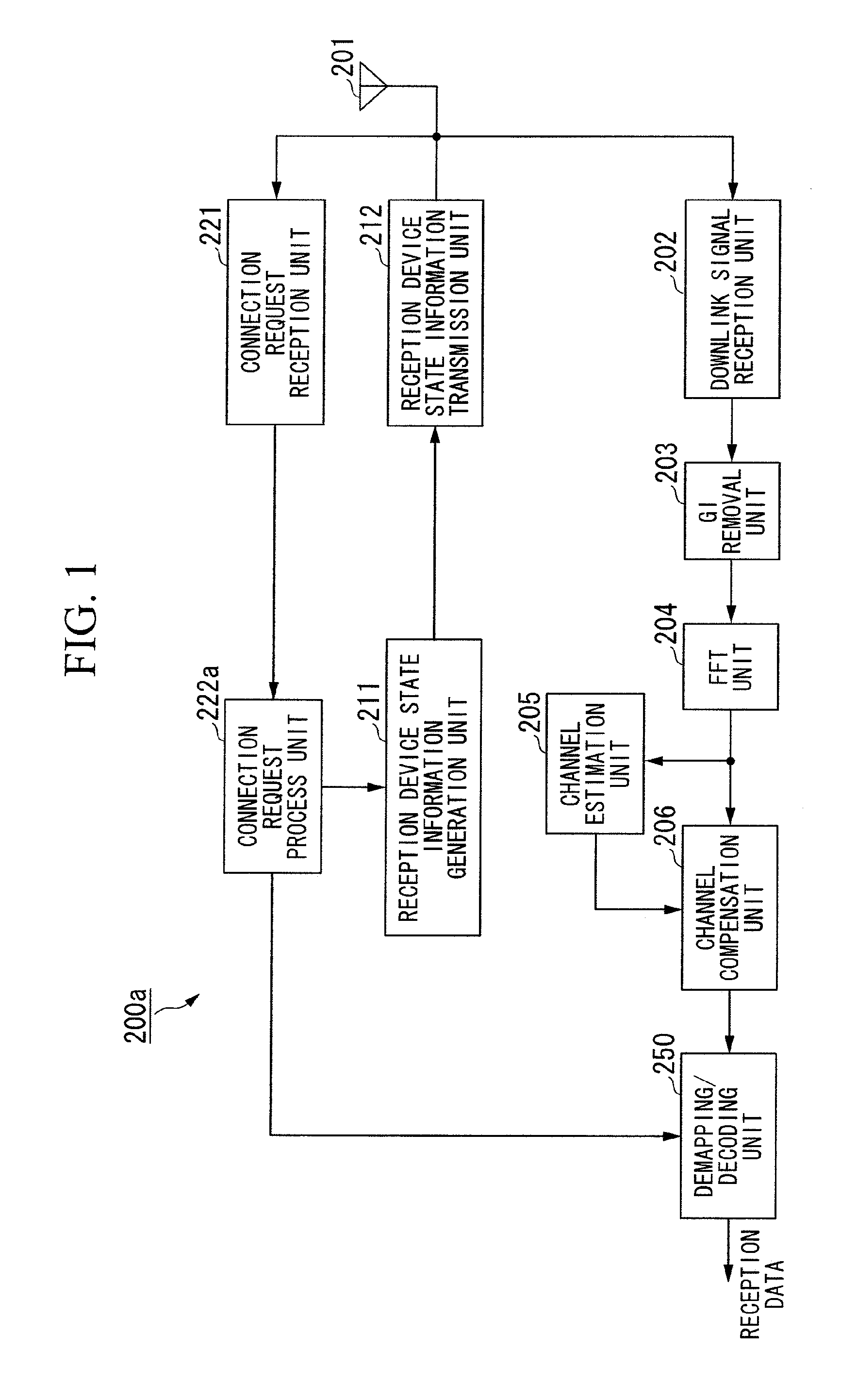
[0066]FIG. 1 is a schematic block diagram illustrating a configuration of the reception device 200a according to the first embodiment of the present invention.

[0067]The reception device 200a includes: a downlink signal reception unit 202; a GI removal unit 203; an FFT unit 204; a channel estimation unit 205; a channel compensation un...

second embodiment

[0135]Hereinafter, a second embodiment of the present invention is explained. The second embodiment is an example of a radio communication system that adaptively determines a mapping method based on a QoS (Quality of Service).

[0136]FIG. 12 is a schematic block diagram illustrating a configuration of a reception device according to a second embodiment of the present invention.

[0137]A reception device 200b of the second embodiment differs from the reception device 200a of the first embodiment in that the connection request process unit 222a of the reception device 200a is replaced with a connection request process unit 222b. Since other process units are the same as those included in the reception device 200a of the first embodiment, explanations are given using the same reference numerals. Additionally, since the configuration of the transmission device 300 is the same as that of the transmission device 300 of the first embodiment, explanations are given using the same reference nume...

third embodiment

[0148]Hereinafter, a third embodiment of the present invention is explained The third embodiment is an example of a radio communication system that determines an optimal signal detection process based on an allowable maximum delay time.

[0149]FIG. 13 is a schematic block diagram illustrating a configuration of a reception device according to the third embodiment of the present invention.

[0150]A reception device 200c of the third embodiment has the same configuration of the reception device 200a of the first embodiment except that a characteristic comparison unit 232 is newly provided. The other process units are the same as those included in the reception device 200a of the first embodiment, and therefore explanations are given using the same reference numerals. Since the transmission device 300 has the same configuration as that of the first embodiment, explanations are given using the same reference numerals.

[0151]Hereinafter, operations of the maximum iteration number determinatio...


PUM


Abstract

A reception device (200a) transmits reception device state information indicating a modulation scheme with which the reception device is compatible, and a channel encoding method. Based on the reception device state information received, a transmission device determines a mapping method for a downlink signal to be transmitted to the reception device (200a). When the reception device (200a) is compatible with BICM-ID, the reception device (200a) transmits reception device state information indicating that the reception device (200a) is compatible with the BICM-ID. Accordingly, the backward compatibility with a communication system using gray mapping can be maintained, and the BICM-ID can be applied.

Description

TECHNICAL FIELD[0001]The present invention relates to a radio communication system, a radio communication method, and a communication device. Particularly, the present invention relates to a radio communication system, a radio communication method, and a communication device for performing a modulation process based on a multilevel modulation.[0002]Priority is claimed on Japanese Patent Application No. 2008-234891, filed Sep. 12, 2008, the content of which is incorporated herein by reference.BACKGROUND ART[0003]Recently, a wideband is assigned to a wireless communication system for high-capacity transmission. However, there is a problem in that the transmission power increases in proportion to the bandwidth. To achieve communication satisfying the low reception power and a low error rate of transmission data, a reception process called a turbo principle has been developed. The turbo principle is a reception process that improves the error rate characteristics by repeating a process ...

Claims


Application Information

Patent Timeline
Patent Type & Authority Applications(United States)
IPC IPC(8): H04L27/00
CPCH03M13/25H03M13/27H03M13/2957H04L27/0008H03M13/6525H04L1/005H04L1/006H03M13/6325
Inventor NAKANO, HIROSHIYOKOMAKURA, KAZUNARIHAMAGUCHI, YASUHIRO
Owner SHARP KK
Why Eureka
Try Eureka