Method for controlling deflection in structural member

Inactive Publication Date: 2011-07-07
OKUMA CORP
View PDF18 Cites 2 Cited by
  • Summary
  • Abstract
  • Description
  • Claims
  • Application Information

AI Technical Summary

Benefits of technology

[0012]With the configuration of the aforementioned method according to the first aspect of the present invention, a force applied to the structural member can be cancelled out by rotation torque generated in the structural member, so that deflection of the structural member can be effectively controlled. In particular, since there is no need to install a heavy fixed member or the like outside the structural member, deflection control can be realized with a compact apparatus without requiring an increase in the size and the cost.
[00

Problems solved by technology

This reaction force induces vibration, which may lead to loss of accuracy in the machine.
Although deflection of the structural member can be controlled by increasing the second moment of cross sectional area of the structural member itself, it leads to an increase in size and cost of the machine.
In the above configuration, it is difficult to adapt this actuator to a structure in which a heavy weighted movable member travels in the horizontal direction, such as a machine tool including a saddle which moves in the horizontal direction a

Method used


Image

  • Method for controlling deflection in structural member
  • Method for controlling deflection in structural member

Examples


Example

[0017]With reference to the accompanying drawing, one exemplary embodiment of the present invention will be described.

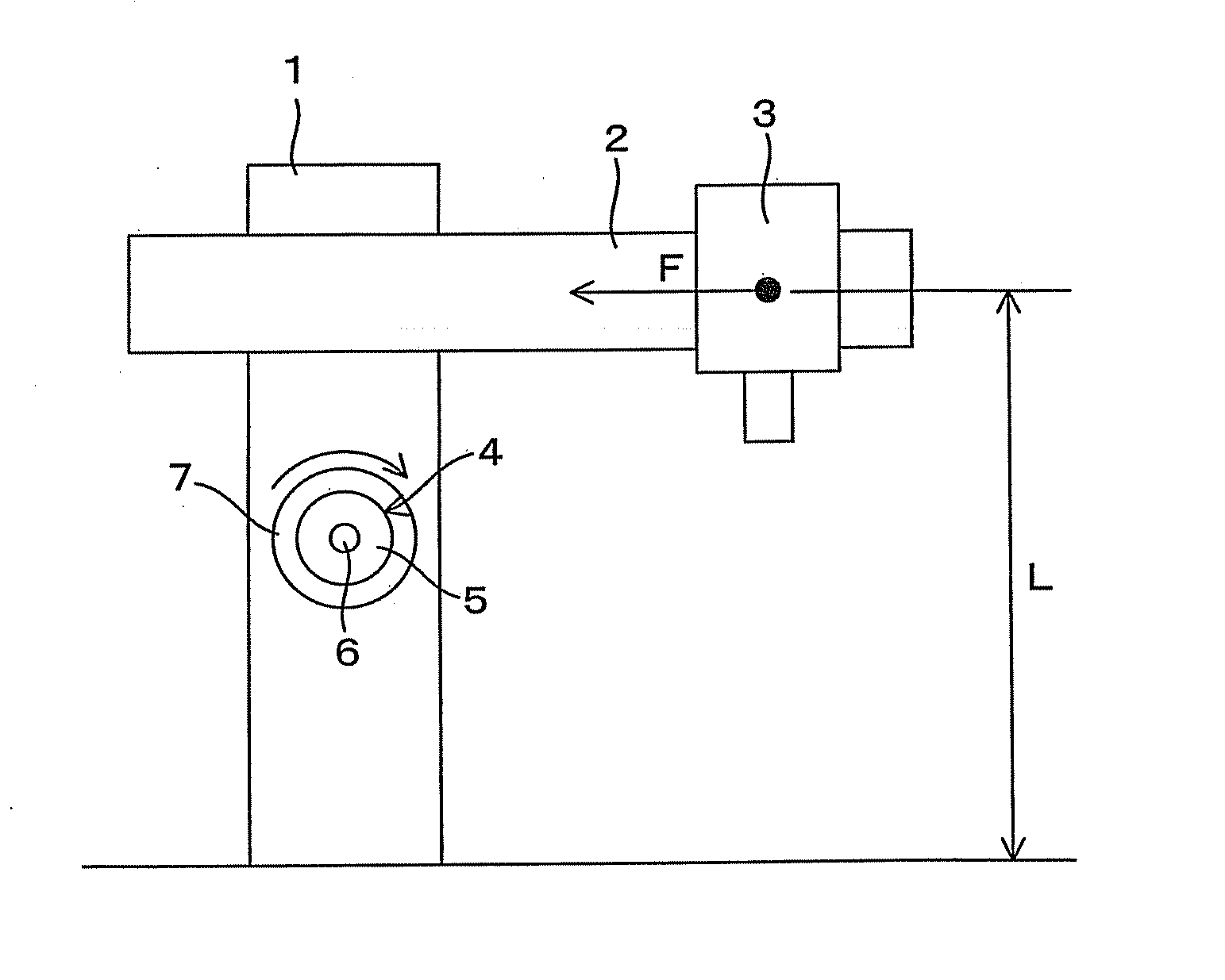
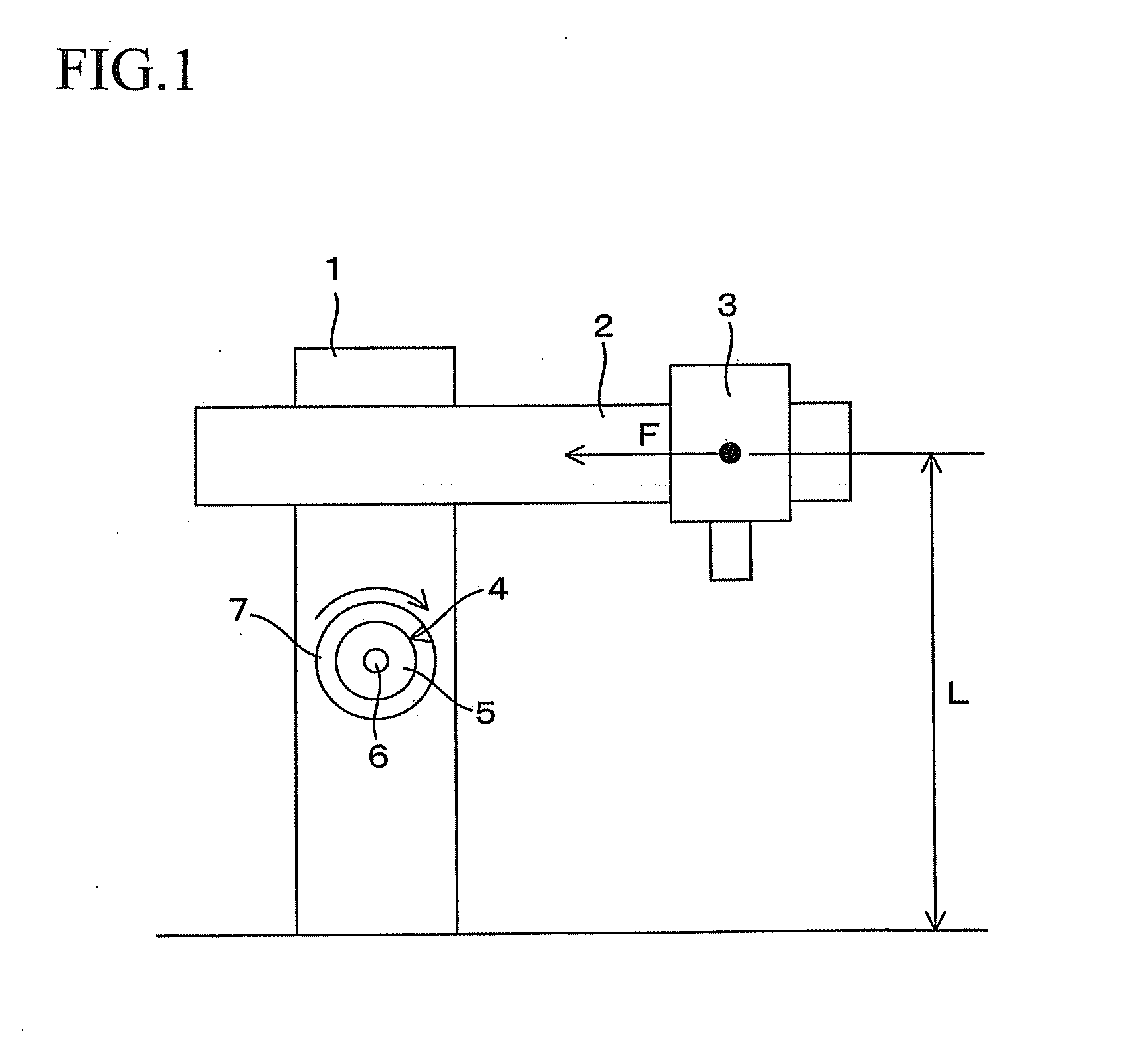
[0018]Referring to FIG. 1, the reference number 1 denotes a columnar structural member provided on a machine. A guide member 2 is horizontally provided at an upper part of the structural member 1, and a movable member 3 is supported on the guide member 2 and capable of moving in the horizontal direction. A double column machining center is given as an example of this machine. In the above configuration, the structural member 1 corresponds to a column, the guide member 2 corresponds to a cross rail, and the movable member 3 corresponds to a saddle.

[0019]A motor 4 is incorporated into the structural member 1 below the guide member 2. A stator 5 of the motor 4 is connected to the structural member 1, whereas a disc 7 having a mass as a load inertia applying device is connected to a rotor 6 of the motor 4. Therefore, when the motor 4 is driven to rotate, rotation torque ...


PUM

PropertyMeasurementUnit
Forceaaaaaaaaaa
Inertiaaaaaaaaaaa
Torqueaaaaaaaaaa

Abstract

A method for controlling deflection caused in a structural member when a force is applied to the structural member is described. The method includes a step of generating rotation torque in the structural member in such a direction as to cancel out the force applied to the structural member. The rotation torque is generated by a motor and a load inertia applying device such as a disc connected to the rotor. A stator of the motor is connected to the structural member and the load inertia applying device applies load inertia to a rotor of the motor.

Description

[0001]This application claims the entire benefit of Japanese Patent Application Number 2010-001465 filed on Jan. 6, 2010, the entirety of which is incorporated by reference.BACKGROUND OF THE INVENTION[0002]1. Field of the Invention[0003]The present invention relates to a method for controlling deflection caused in structural members of various machines such as machine tools.[0004]2. Description of Related Art[0005]In various machines including machine tools, if a movable member capable of moving along a structural member is provided, deflection may occur in the structural member due to a reaction force caused by an acceleration or deceleration of the movable member. For example, in the case of a double column machining center as an example of a machine tool, which includes: a bed, columns as a structural member which vertically extend on the bed, a horizontal cross rail bridging between the columns at front surfaces of the columns and capable of moving in the vertical direction, and...

Claims


Application Information

Patent Timeline
IPC IPC(8): F16M11/00
CPCB23Q15/22Y10T409/309744G05B2219/49186G05B19/404
Inventor HASEBE, TAKAONORIHISA, TAKASHI
Owner OKUMA CORP
Why Eureka
Try Eureka