Lamp structure

a technology of lamp structure and housing, which is applied in the direction of point-like light source, semiconductor devices for light sources, lighting and heating apparatus, etc., can solve the problems of difficult mold fitting to the environment, high manufacturing cost and difficult assembly, and difficult to adjust the housing of this conventional smd led type lamp to fit the environment, etc., to achieve easy assembly, low cost, and better illumination

Inactive Publication Date: 2011-07-07
HUANG YING FANG
View PDF5 Cites 53 Cited by
  • Summary
  • Abstract
  • Description
  • Claims
  • Application Information

AI Technical Summary

Benefits of technology

[0009]Since the aluminum extrusion pipe can be cut into any desired length and extruded into any shapes, such as arc shape, circular shape, wavy shape, and etc, the lamp structure of the present invention can be adjusted in size and shape to fit the environment in which it is to be installed. Furthermore, as compared with the conventional lamp, the lamp structure of the present invention is low in cost and easy to assemble. Especially, the

Problems solved by technology

The housing of a conventional SMD (surface mount device) LED type lamp essentially is made by bending a board into a box structure, so its shape is fixed and unchangeable, it is high in manufacturing cost and difficult to assemble.
More particularly, the housing of this conventional SMD LED type lamp is difficult to be adjusted to fit the environment in which the lamp is to be installed.
While making a new mould to f

Method used


Image

  • Lamp structure
  • Lamp structure
  • Lamp structure

Examples


first embodiment

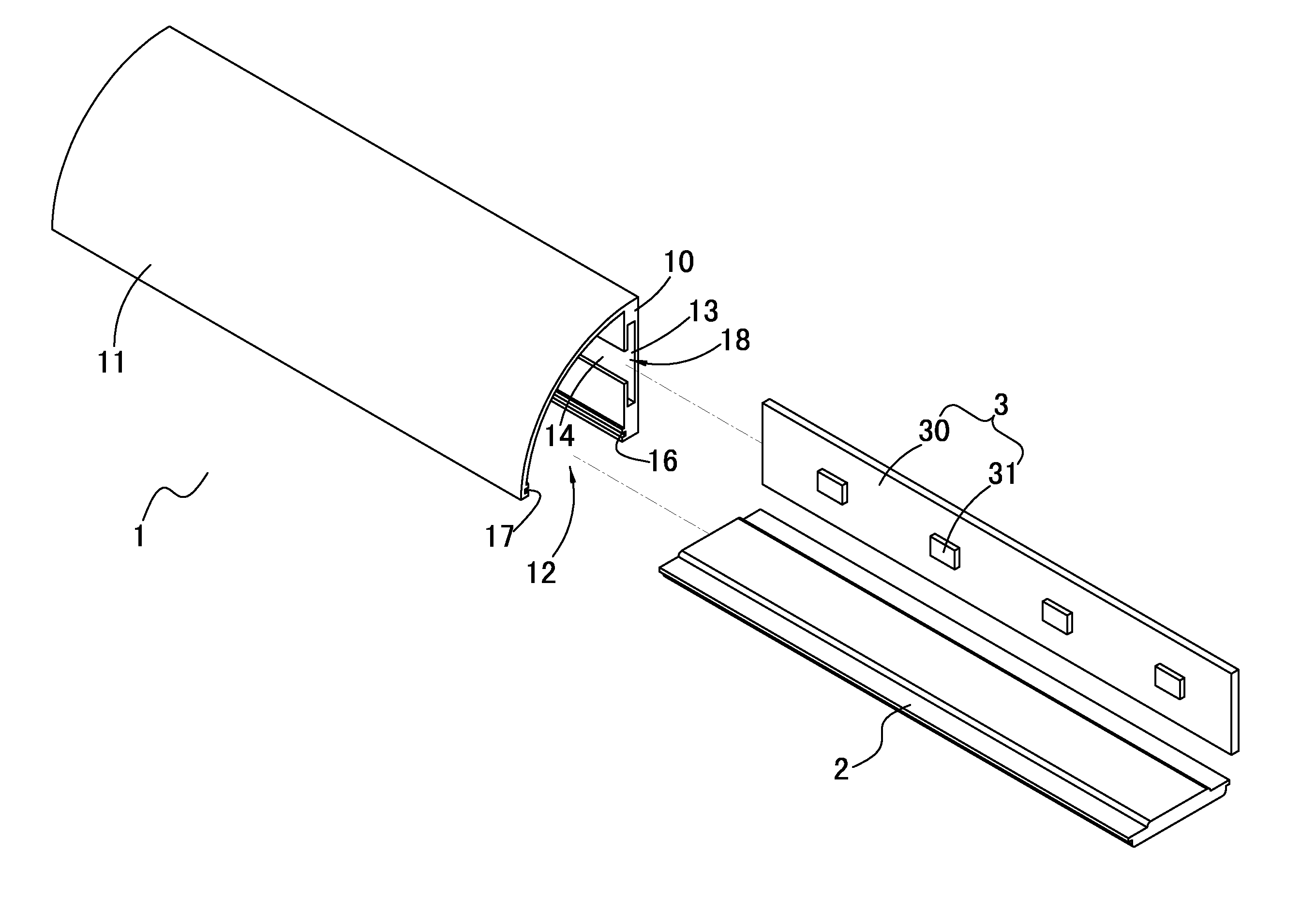
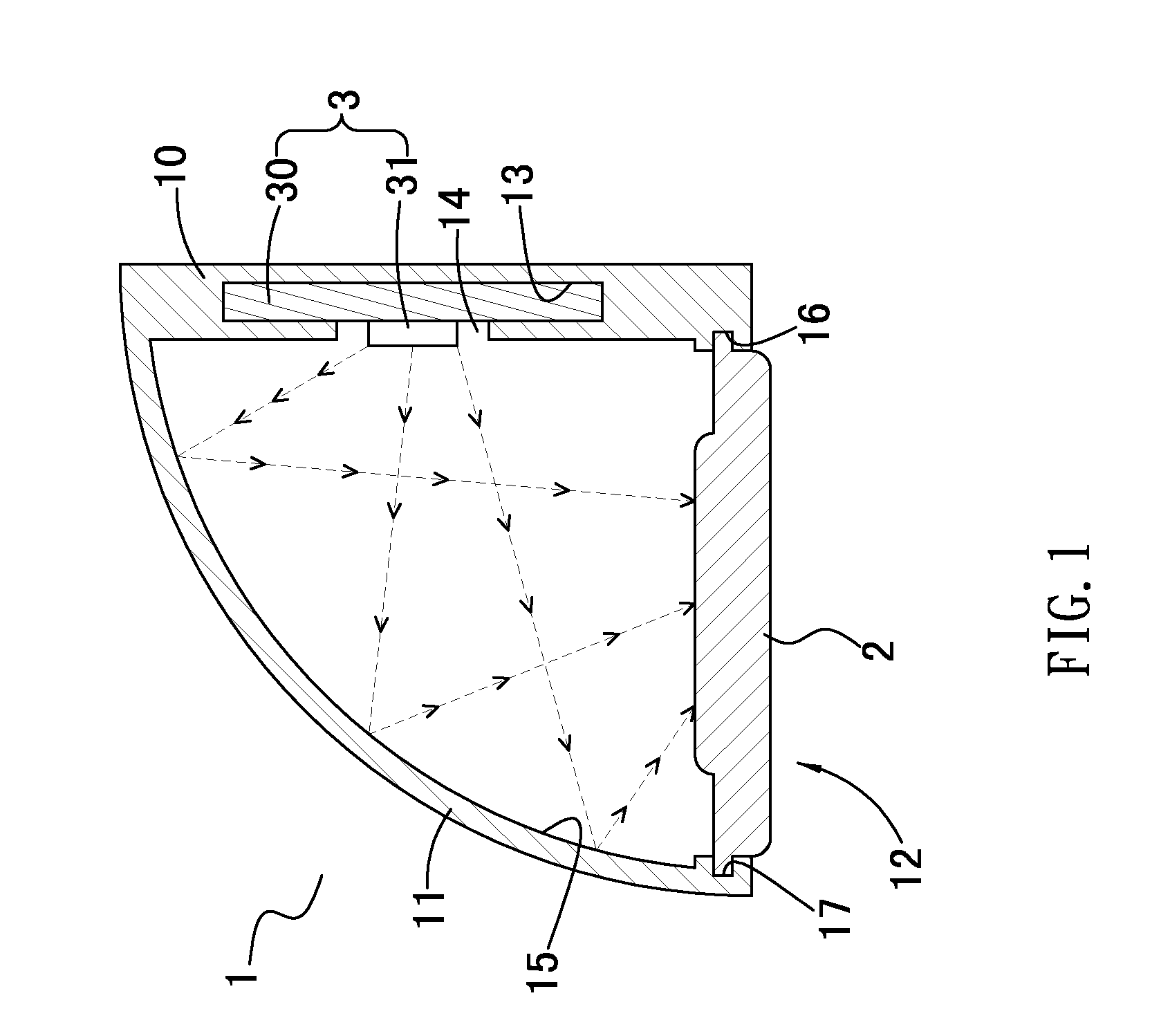
[0022]FIG. 1 shows a lamp structure in accordance with the present invention, the lamp structure comprises: an aluminum extrusion pipe 1, a light transmission cover 2 and a light emitting member 3.

[0023]The aluminum extrusion pipe 1 is an elongated structure and axially provided with a first sidewall 10, a second sidewall 11 and an opening 12. The first sidewall 10 is a vertical structure formed with an engaging groove 13 which is in communication with a through hole 14 defined in an inner surface of the first sidewall 10. The second sidewall 11 is an arc-shaped structure extending from the top end of the first sidewall 10. The opening 12 is defined between the first and second sidewalls 10, 11 and located at the lower side of the aluminum extrusion pipe 1. The second sidewall 11 is provided on a surface thereof facing the first sidewall 10 and the opening 12 with a light reflection surface 15. The first and second sidewalls 10, 11 are formed in their opposite surfaces close to the ...

second embodiment

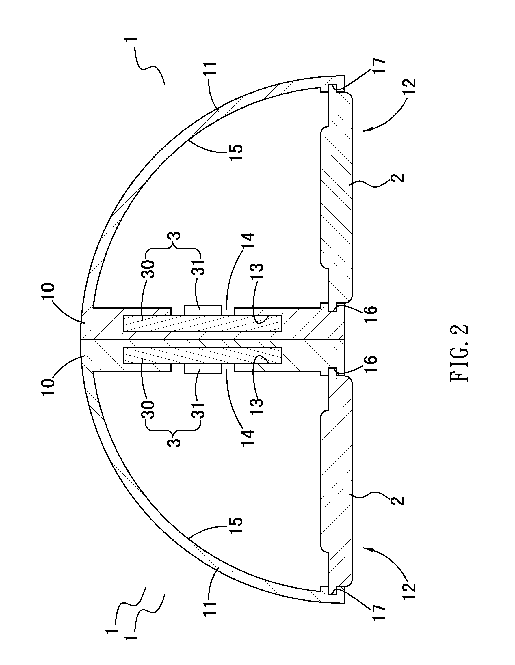
[0028]FIG. 3 shows a lamp structure in accordance with the present invention, wherein the aluminum extrusion pipe 1b is an elongated structure and axially provided with two sidewalls 10b, two second sidewalls 11b and two openings 12b.

[0029]The first two sidewalls 10b are vertically arranged in parallel to each other. Each of the first sidewalls 10b is formed with an engaging groove 13b for accommodation of a flexible circuit board 30b of a light emitting member 3b. In an inner surface of the respective first sidewalls 10b is formed a through hole 14b which is in communication with the engaging groove 13b and provided for accommodation of the light sources 31b of the light emitting member 3b. In an outer surface of the respective first sidewalls 10b is formed an inserting hole 16b in communication with the corresponding engaging groove 13b, so that the light emitting member 3b can be placed in the engaging groove 13b via the inserting hole 16b. In a bottom edge of the respective fir...


PUM


Abstract

A lamp structure comprises an aluminum extrusion pipe, a light transmission cover, and a light emitting member. The aluminum extrusion pipe is axially provided with at least one first sidewall, one second sidewall and one opening, the first sidewall is formed with at least an engaging groove in communication with a through hole in the first sidewall, the second sidewall is provided with at a light reflection surface. The light transmission cover is mounted on the aluminum extrusion pipe to cover the opening. The light emitting member includes a flexible circuit board and plural light sources, the light sources are arranged spaced apart on the flexible circuit board, the light of the light sources of the light emitting member are focused on the light transmission cover through reflection by the light reflection surface, and finally projected out of the aluminum extrusion pipe after passing through the light transmission cover.

Description

BACKGROUND OF THE INVENTION[0001]1. Field of the Invention[0002]The present invention relates to a lamp structure, and more particularly to a low cost lamp structure which is flexible in shape, easy to assemble and can produce better illumination without light spots.[0003]2. Description of the Prior Art[0004]The housing of a conventional SMD (surface mount device) LED type lamp essentially is made by bending a board into a box structure, so its shape is fixed and unchangeable, it is high in manufacturing cost and difficult to assemble. More particularly, the housing of this conventional SMD LED type lamp is difficult to be adjusted to fit the environment in which the lamp is to be installed. While making a new mould to fit the environment where the lamp is to be installed is uneconomical.[0005]In addition, the light sources of the conventional SMD LED type lamp are installed in the housing of the lamp, and the light transmission cover is disposed at the opening of the housing, the l...

Claims


Application Information

Patent Timeline
IPC IPC(8): F21V1/00
CPCF21V7/0008F21V7/09F21Y2103/003F21Y2101/02F21V15/013F21Y2103/10F21Y2115/10
Inventor HUANG, YING FANG
Owner HUANG YING FANG
Why Eureka
Try Eureka