Annuloplasty devices and methods of deliver therefor

a technology of annuloplasty and a catheter, which is applied in the field of percutaneous repair of the mitral valve, can solve the problems of ultimate weakening of the left ventricle, increased total stroke volume, and decreased cardiac output, and achieves the effect of facilitating target-specific anchoring and steering of the steerable catheter

Active Publication Date: 2011-07-07
VALTECH CARDIO LTD
View PDF101 Cites 199 Cited by
  • Summary
  • Abstract
  • Description
  • Claims
  • Application Information

AI Technical Summary

Benefits of technology

[0096]In some embodiments of the present invention, a delivery system is provided for positioning and anchoring of the annuloplasty structures described herein to the annulus of the patient. The delivery system comprises an advancement catheter housing (a) the annuloplasty structure in a distal portion thereof, and (b) a steerable catheter disposed proximally with respect to the annuloplasty structure. A plurality of guide members are reversibly coupled to the annuloplasty structure and to the steerable catheter. These guide members facilitate steering of the steerable catheter toward specific locations along the annuloplasty structure. Typically, by pulling on the proximal end of a given guide member, the distal end of the catheter is steered toward a given location of annuloplasty structure.
[0097]Once the distal end of the catheter is disposed in proper orientation with respect to the given location along the annuloplasty structure, an anchoring device, e.g., an anchor or a suture, is delivered through the steerable catheter and toward the given location. The annuloplasty structure is then anchored to the annulus via the anchoring device. Thus, the steerable catheter and guide members facilitate target-specific anchoring of the annuloplasty structure to the annulus.
[0200]reducing the perimeter of the longitudinal member by applying a compression force to the longitudinal member.125. The method according to inventive concept 124, further comprising facilitates sliding of the first end of the flexible member with respect to the second end in the second direction, even in the absence of a force applied to the contracting wire.126. The method according to inventive concept 124, further comprising applying a pulling force to the contracting member, and wherein applying the compression force to the longitudinal member comprises:
[0204]facilitating sliding of the first end of the longitudinal member with respect to the second end in the first direction, and
[0209]responsively to the applying the pulling force, facilitating sliding of the first end of the longitudinal member with respect to the second end in the first direction.

Problems solved by technology

Mitral regurgitation of blood from the left ventricle into the left atrium results in increased total stroke volume and decreased cardiac output, and ultimate weakening of the left ventricle secondary to a volume overload and a pressure overload of the left atrium.

Method used


Image

  • Annuloplasty devices and methods of deliver therefor
  • Annuloplasty devices and methods of deliver therefor
  • Annuloplasty devices and methods of deliver therefor

Examples


Embodiment Construction

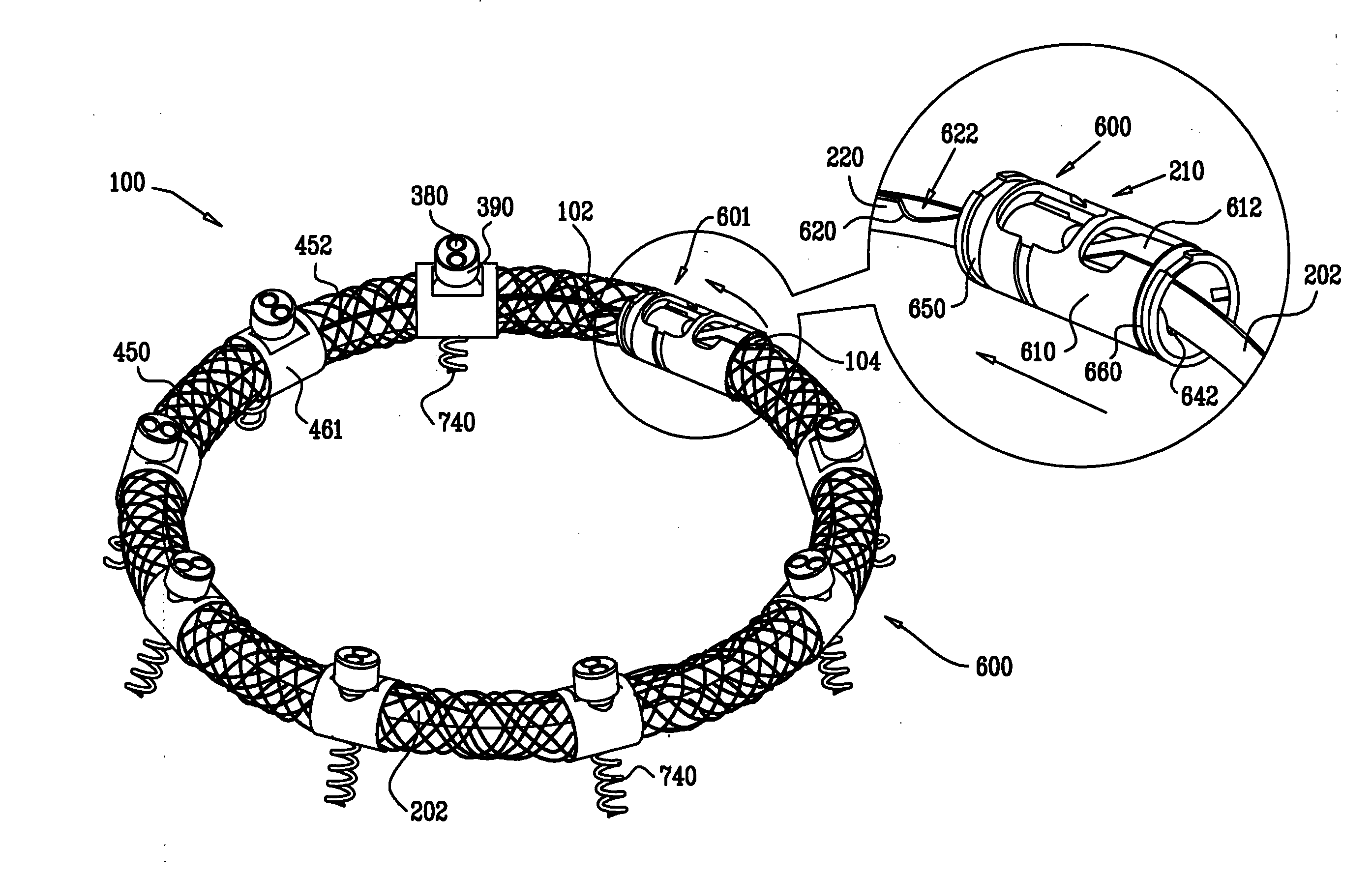
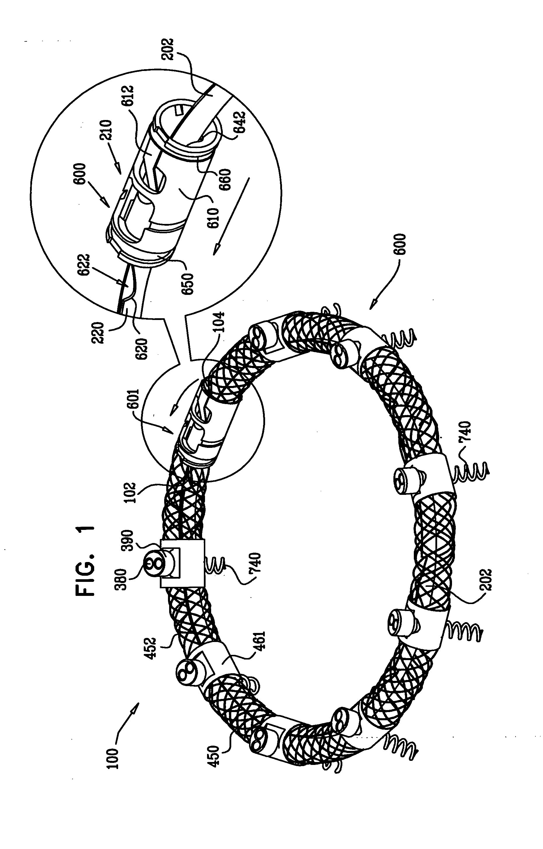
[0227]Reference is now made to FIG. 1, which is a schematic illustration of an annuloplasty structure 100, e.g., at least one elongate segment or tubular element, comprising a plurality of compressible subunits 450 and a plurality of anchor mounts 461, in accordance with an embodiment of the present invention. Structure 100 comprises a modular annuloplasty structure in which the plurality of compressible subunits 450 are alternately disposed with respect to the plurality of anchor mounts 461. Typically, structure 100 comprises an implant shaped to define a tubular structure having a cross-section of any suitable shape, e.g., circular or elliptical. Compressible subunits 450 are shaped to define a hollow lumen and comprise a braided mesh 452 (e.g., wire or polyester), by way of illustration and not limitation. For example, compressible subunits 450 may comprise a plurality of coils, braided structures, stent-shaped struts, or accordion- or bellows-shaped structures. A ratchet mechani...


PUM


Abstract

Apparatus is provided, including a tube (421) shaped to define a tube lumen at least one implant (100) reversibly coupled to the tube (421), and configured for implantation within a body of a patient. The apparatus also comprises two or more longitudinal guide members (470) disposed at least in part along a distal portion of the tube (421), the longitudinal guide members (470) having distal portions thereof configured to be reversibly coupled to the implant (100), and arranged such that application of a force to a first one of the longitudinal guide members (470) steers the distal portion of the tube (421) toward a first location along the implant (100), and application of a force to a second one of the longitudinal guide members (470) steers the distal portion of the tube (421) toward a second location along the implant (100). Other embodiments are also described.

Description

CROSS-REFERENCES TO RELATED APPLICATIONS[0001]The present application claims priority from U.S. Provisional Patent Application 61 / 132,295 to Gross et al., entitled, “Annuloplasty devices and methods of delivery therefor,” filed Jun. 16, 2008, which is incorporated herein by reference.FIELD OF THE INVENTION[0002]The present invention relates in general to valve repair. More specifically, the present invention relates to percutaneous repair of a mitral valve of a patient.BACKGROUND OF THE INVENTION[0003]Ischemic heart disease causes mitral regurgitation by the combination of ischemic dysfunction of the papillary muscles, and the dilatation of the left ventricle that is present in ischemic heart disease, with the subsequent displacement of the papillary muscles and the dilatation of the mitral valve annulus.[0004]Dilation of the annulus of the mitral valve prevents the valve leaflets from fully coapting when the valve is closed. Mitral regurgitation of blood from the left ventricle int...

Claims


Application Information

Patent Timeline
Patent Type & Authority Applications(United States)
IPC IPC(8): A61F2/24
CPCA61B17/3468A61B2017/00243A61F2220/0008A61F2/2466A61F2250/001A61F2/2445A61F2/2442
Inventor GROSS, AMIRBEINART, IFTAHMILLER, ERANCABIRI, OZELIACHAR, ELIAHULILACH, NIRGROSSFELD, RAMGOLOM, DMITRYMEYER-BRODNITZ, GIDEONMOSAIUF, ARNON
Owner VALTECH CARDIO LTD
Why Eureka
Try Eureka