
Frame assembly having stile and rail tabs for coupling stile and rail members together

a frame and rail technology, applied in the field of frame assemblies, can solve the problems of time and the cross-section of the rail member is not uniform, and the use of the attachment member adds cost to manufacture the frame assembly, so as to achieve the effect of reducing cost and time to manufactur

Active Publication Date: 2011-07-14
QUANEX HOMESHIELD LLC
View PDF10 Cites 25 Cited by
  • Summary
  • Abstract
  • Description
  • Claims
  • Application Information

AI Technical Summary

Benefits of technology

[0011]The bending of the stile tab around the interior wall of the rail member and bending the rail tab around the exterior wall of the stile member prevents the stile member and the rail member from separating from each other. The bending of the stile tab and the rail tab also eliminates the need for a separate attachment component to couple the stile member and the rail member together. Elimination of the separate attachment component minimizes cost and time to manufacture the frame assembly.

Problems solved by technology

The use of the attachment member adds cost to manufacture the frame assemble due to the cost of the attachment member.
The formation of the slot in the stile members adds time and costs to manufacture the frame assembly.
The cross-section of the rail member is not uniform over an entire length because the end of the rail member must be narrowed to allow the rail member to be received within the stile member.
As such, the stile and rail members do not have uniform cross-sections thus increasing costs to manufacture the frame assembly because the stile and rail members must be formed independent of one another.
Furthermore, completely disposing the rail member within the stile member results in limited engagement between the stile and rail members when coupled together.
The limited engagement between the stile and rail members limits the ability of the frame assembly to resist separating when normal forces act on the frame assembly.

Method used


Image

  • Frame assembly having stile and rail tabs for coupling stile and rail members together
  • Frame assembly having stile and rail tabs for coupling stile and rail members together
  • Frame assembly having stile and rail tabs for coupling stile and rail members together

Examples


Embodiment Construction

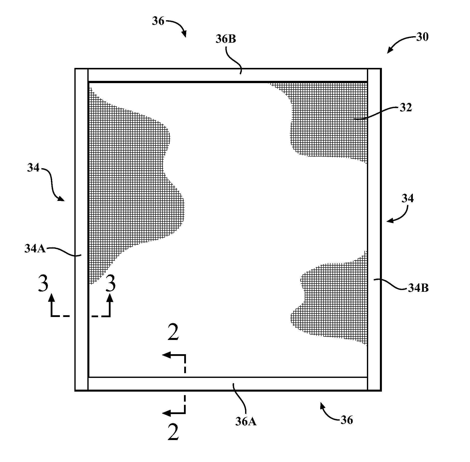
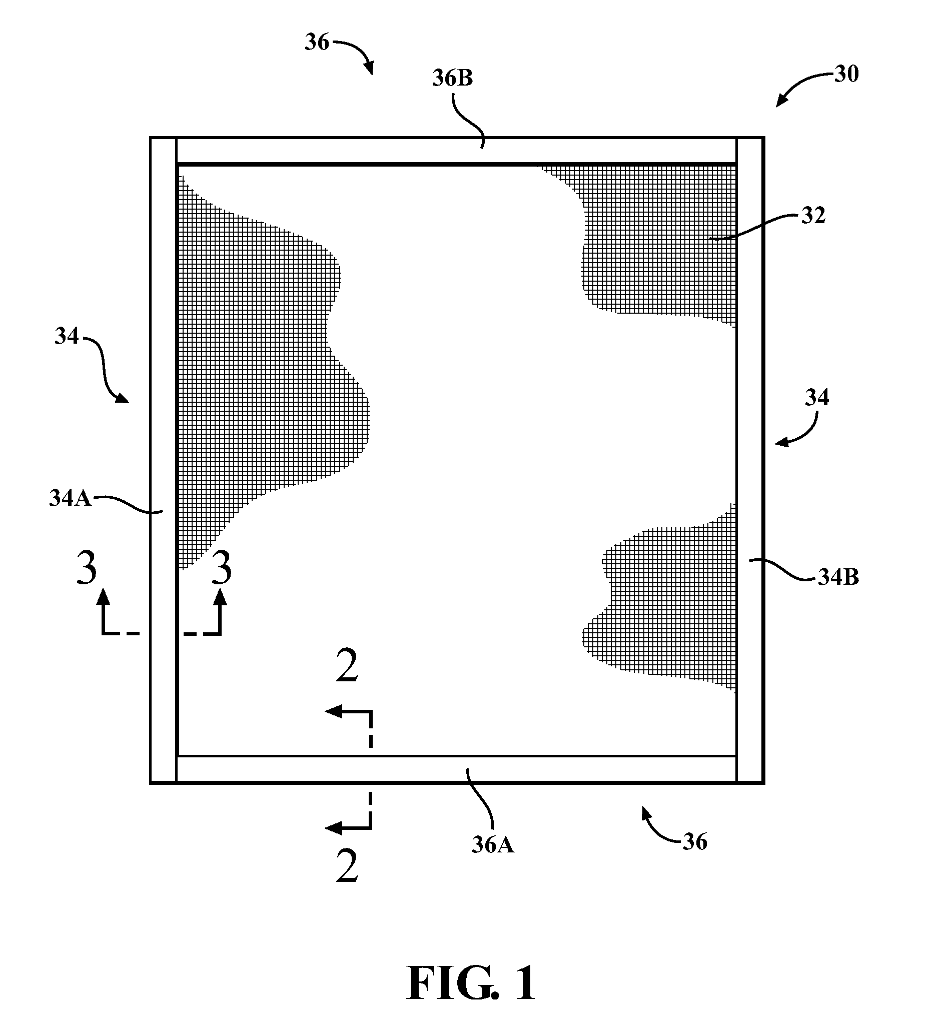
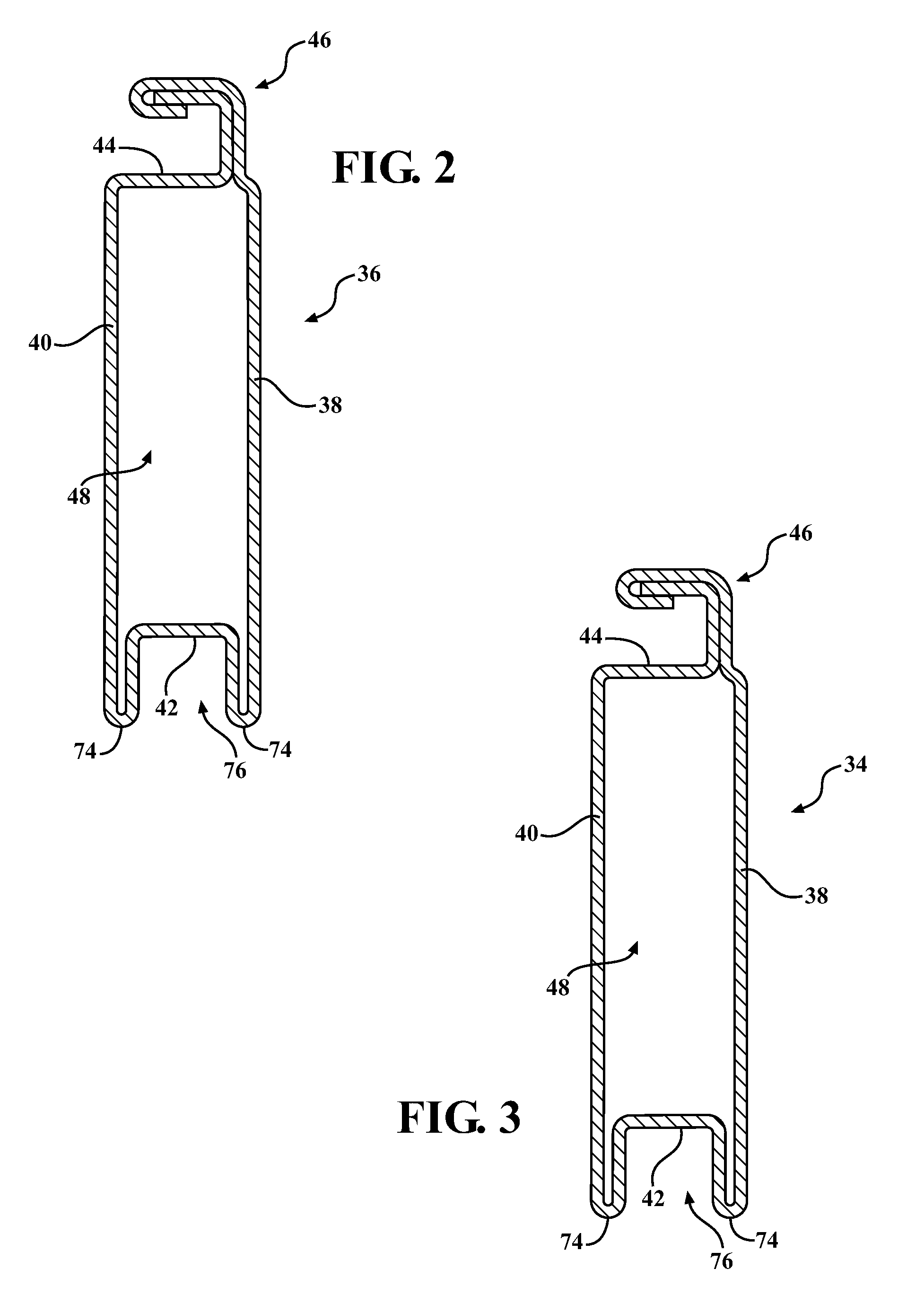
[0041]Referring to the Figures, wherein like numerals indicate corresponding parts throughout the several views, a frame assembly is generally shown at 30. With reference to FIG. 1, the frame assembly 30 typically supports a fenestration article 32, such as a screen cloth, a glass pane, and / or a plastic panel. However, it should be understood that the frame assembly 30 may support any desired article other than the fenestration article 32. Typically, the frame assembly 30 is disposed adjacent an opening defined by a structure, such as a building or house for covering the opening.

[0042]The frame assembly 30 comprises at least one stile member 34 and at least one rail member 36. Generally, the rail member 36 is coupled substantially transverse to the stile member 34. Said differently, the coupling of the rail member 36 to the stile member 34 defines an angle of 90 degrees between the stile member 34 and the rail member 36. It is to be appreciated that the stile member 34 and the rail ...


PUM

PropertyMeasurementUnit
Lengthaaaaaaaaaa

Abstract

A frame assembly supports a fenestration article. The frame assembly comprises a stile member and a rail member coupled substantially transverse to the stile member. A stile tab extends axially from the stile member and a rail tab extends axially from the rail member. The stile tab is bent around the rail member and the rail tab is bent around the stile member for coupling the stile member to the rail member.

Description

CROSS REFERENCE TO RELATED APPLICATION[0001]This application claims priority to and all the advantages of U.S. Provisional Patent Application Ser. No. 61 / 335,932, which was filed on Jan. 13, 2010.BACKGROUND OF THE INVENTION[0002]1. Field of the Invention[0003]The invention generally relates to a frame assembly and, more specifically, to a frame assembly for supporting a fenestration article.[0004]2. Description of the Related Art[0005]Frame assemblies for windows or doors, which support an article, such as screen cloth or a pane of glass, are known in the art and have been widely used by window manufacturers. Generally, the frame assemblies are disposed adjacent to an exterior side of the window or door. A typical frame assembly includes a pair of stile members and a pair of rail members. The stile and rail members are coupled together to form the frame assembly.[0006]Typically, the stile and rail members are coupled together by a separate attachment component such as a fastener, an...

Claims


Application Information

Patent Timeline
IPC IPC(8): E06B3/96E04C2/38
CPCE06B9/52Y10T29/49826Y10T29/49627
Inventor SAWYERS, JEFFREY V.JENSEN, BRIANISAACS, JOSEPH D.PICH, RONALD J.
Owner QUANEX HOMESHIELD LLC
Learn More