Eureka AIR delivers breakthrough ideas for toughest innovation challenges, trusted by R&D personnel around the world.

Sensor For Measuring Stresses Including A Layer Of A Magnetoelastic Material And A Method For Producing The Layer

a magnetoelastic material and stress sensor technology, applied in the direction of force/torque/work measurement apparatus, instruments, manufacturing tools, etc., can solve the problems of high magnetoelastic sensitivity, inconvenient, and inability to maintain a static magnetic field, and achieve good stress-measuring properties

Active Publication Date: 2011-07-14
ABB (SCHWEIZ) AG
View PDF6 Cites 9 Cited by
  • Summary
  • Abstract
  • Description
  • Claims
  • Application Information

AI Technical Summary

Benefits of technology

[0016]The object of the present invention is to provide a method for producing a layer of a magnetoelastic material having good stress-measuring properties, which method overcomes the above mentioned disadvantages with electroplating.

Problems solved by technology

A soft magnetic material differs from a hard magnetic material in that it cannot maintain a static magnetic field after it has been magnetized.
Microstructures with grains larger than 10000 nm tend to have higher magnetoelastic sensitivity, which is not favorable when trying to achieve the above-mentioned wide measuring range.
However, there are some disadvantages with the electroplating method.
One disadvantage is that it takes a very long time to apply thick layers.
To apply such a thick layer with electroplating takes hours.
Accordingly, electroplating is not a commercially attractive method for applying the layer on the load-carrying member.
A further disadvantage with electroplating is that it can lead to a reduced strength of the material on which the layer is applied, and in particular for hardened materials, such as carburized steel.
Layer application with atom-by-atom methods, such as physical or chemical vapour deposition, are slow and have limitations when building layers tens or hundreds of microns thick.
A well-known problem with many powder metallurgical methods is oxidation due to the heating of the powder and the fact that the metal powder is in contact with air during the spraying.
Due to the inhomogenity of the produced coating and relatively high temperatures upon deposition of the layer, high speed thermal spray techniques are not suitable to achieve a homogeneous nanocrystalline layer of a desired uniformity of chemical composition and grain sizes.
Thus, high velocity thermal spray techniques cannot be used to produce the homogeneous nanocrystalline layer needed for carrying out the method described in WO2007 / 106024.

Method used


Image

  • Sensor For Measuring Stresses Including A Layer Of A Magnetoelastic Material And A Method For Producing The Layer
  • Sensor For Measuring Stresses Including A Layer Of A Magnetoelastic Material And A Method For Producing The Layer
  • Sensor For Measuring Stresses Including A Layer Of A Magnetoelastic Material And A Method For Producing The Layer

Examples


Embodiment Construction

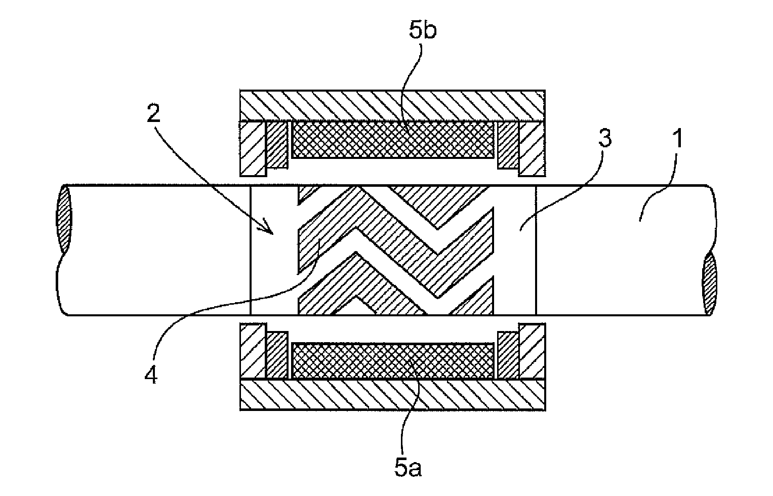
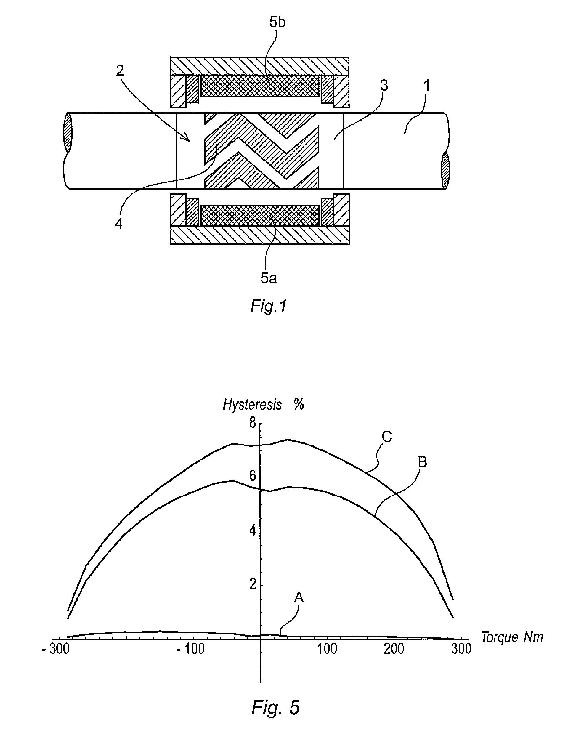
[0048]FIG. 1 shows an example of a measuring device including a load-carrying member, in the form of a rotary shaft 1, which is arranged to transmit a torque in any kind of mechanical transmission. The device is adapted to measure torques applied to the load-carrying member. The load-carrying member is made of a material with sufficient stiffness, for example of steel. A magnetoelastic region 2 is provided on the shaft 1. The magnetoelastic region 2 comprises a first layer 3 of a magnetoelastic material, which has a substantially continuous extension and thickness in said region 2. In this embodiment, the magnetoelastic layer 3 is formed by spraying and is mainly composed of iron and nickel. A second layer 4 in the form of a continuous strip is provided on the first layer 3. The second layer 4 forms a surface pattern on the first layer 3. Further, the measuring device includes windings 5a-b supplying the measuring device with an alternating magnetization field. This type of measurin...


PUM

PropertyMeasurementUnit
melting temperatureaaaaaaaaaa
temperatureaaaaaaaaaa
velocityaaaaaaaaaa

Abstract

A sensor for measuring stresses induced by a force applied to a load-carrying member, including a layer of a magnetoelastic material formed on the load-carrying member is provided. The layer comprises a first phase with an average grain size below 100 nm and a first chemical composition, and a second phase of a distinctly different chemical composition, the first phase being divided by the second phase into regions having an average size in the range of 100-10,000 nm. A method for producing such a layer, including accelerating particles of a soft magnetic and magnetoelastic material having an average size in the range of 10-50 μm towards the surface of the load-carrying member at a velocity of at least 300 m / s such that the average temperature of the accelerated particles is not higher than 500° C. above the melting temperature of the magnetoelastic material, but not lower than 500° C. below the melting temperature.

Description

CROSS-REFERENCE TO RELATED APPLICATIONS[0001]The present application is a continuation of pending International Patent Application PCT / EP2009 / 060721 filed on Aug. 19, 2009 which designates the United States and claims priority from European Patent Application No. 08165077.2 filed on Sep. 25, 2008, the content of which is incorporated herein by reference.FIELD OF THE INVENTION[0002]The present invention relates to a sensor for measuring stresses induced by a force applied to a load-carrying member, wherein the sensor includes a layer of a magnetoelastic material formed on the load-carrying member, and the sensor is arranged to generate a time-varying magnetic field in the magnetoelastic layer, to detect changes in the permeability in the layer, and to determine the induced stresses based on the detected changes in the permeability in the layer. The present invention relates to a method for producing such a layer.BACKGROUND OF THE INVENTION[0003]The sensor measures stresses and / or str...

Claims


Application Information

Patent Timeline
Patent Type & Authority Applications(United States)
IPC IPC(8): G01L3/10G01L1/12B23Q17/00H10N35/00H10N30/01H10N30/853H10N35/01
CPCC23C4/06C23C24/04G01L3/102Y10T29/49764H01L41/47G01L3/103H01L41/125H10N35/101H10N35/01G01L3/10H10N35/00H10N30/853Y02T50/60
Inventor LING, HANSMINIOTAS, ANDRIUS
Owner ABB (SCHWEIZ) AG
Why Eureka
Eureka Blog
Learn More