Boundary Microphone

Inactive Publication Date: 2011-07-14
AUDIO-TECHNICA
View PDF11 Cites 11 Cited by
  • Summary
  • Abstract
  • Description
  • Claims
  • Application Information

AI Technical Summary

Benefits of technology

[0009]In the present invention, the pressure-sensitive switch is physically isolated from the base so that vibration occurring on pressing the switch does not propagate. Such a structure can reduce vibration noise caused by vibration of the boundary microphone body occurring on the switching operation of the pres

Problems solved by technology

Use of a push switch having click feeling generates noise due to vibration of the microphone itself by the switching operation with click feeling.
Unfortunately, some motion such as transfer of documents on the desk may lead to vibration of the boundary microphone 11 and thus generation of noise.
Such a soft support 12, however, causes sinking of the boundary microphone 11 when the user p

Method used


Image

  • Boundary Microphone
  • Boundary Microphone
  • Boundary Microphone

Examples


Embodiment Construction

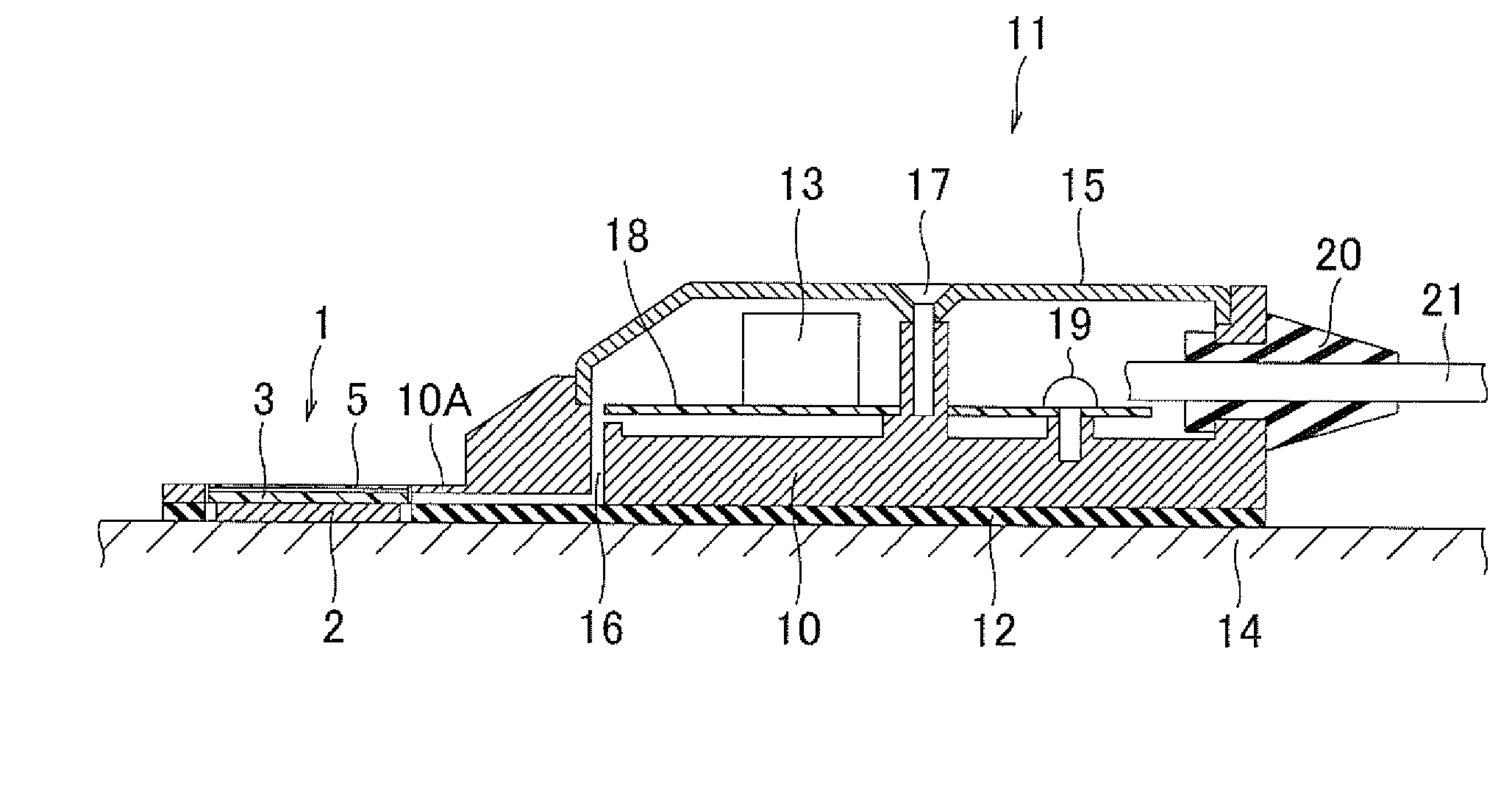
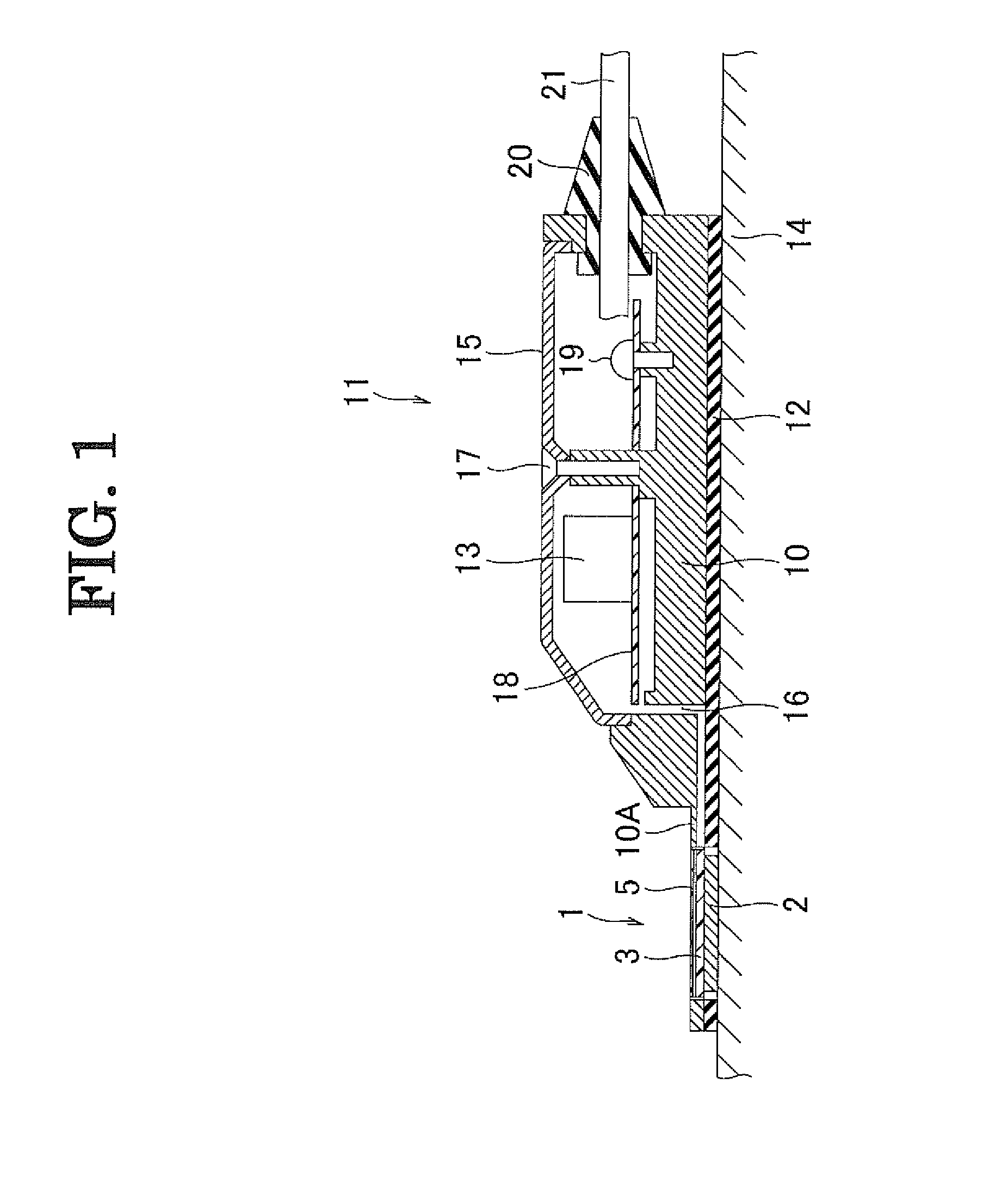
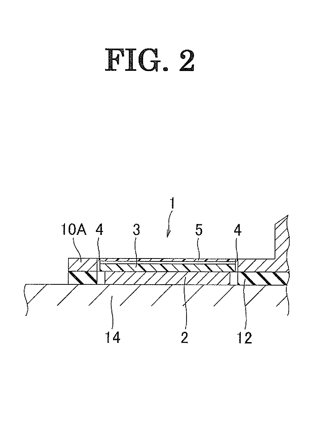
[0014]Embodiments of a boundary microphone in accordance with the present invention will now be described with reference to the attached drawings. With reference to FIG. 1, the boundary microphone 11 primarily includes a flat metal base 10 having an opening on the top; a metal microphone cover 15 having a large number of openings (sound inlet openings), the cover 15 being mounted on the base 10 so as to cover the top face of the base 10; a pressure sensitive switch 1; a switch support 2 supporting the pressure-sensitive switch 1; an external thread 17, a printed circuit board 18 for the boundary microphone 11; and a microphone unit 13. A microphone cord 21 and a cord bush 20 are attached to the tail end (right end in FIG. 1) of the base 10. A support 12 is disposed on the entire bottom surface of the base 10. The boundary microphone 11 is disposed on a desk 14. The support 12 may be composed of a nonflexible material, but preferably be composed of a flexible material that can absorb...


PUM


Abstract

A boundary microphone includes a base, a microphone unit that is mounted onto the base and converts voice into electrical signals, and a pressure-sensitive switch of membrane type for an on/off operation of output signals from the microphone unit. The pressure-sensitive switch is physically isolated from the base, and is supported at the bottom thereof by a switch support comprising a hard material.

Description

TECHNICAL FIELD[0001]The present invention relates to a boundary microphone that has a pressure-sensitive switch switching output signals from a microphone unit and is primarily used on a table.BACKGROUND ART[0002]Boundary microphones have pressure-sensitive switches switching output signals from microphone units and are used on tables. The boundary microphones, which are used on desks or floors in TV studios and conference halls, are also called surface mount microphones (on-surface sound pickup microphones). For example, as is disclosed in Japanese Unexamined Patent Application Publication No. 2008-288933, a boundary microphone is primarily used on a table; thus, a microphone unit and an accompanying circuit are incorporated into a low-profile flat casing in many cases so that its existence is unnoticed.[0003]With reference to FIG. 3, a boundary microphone 11 has a flat, low profile at the periphery and includes a metal base 10 having an opening on the top, a microphone cover 15 t...

Claims


Application Information

Patent Timeline
IPC IPC(8): H04R11/04
CPCH04R3/005H04R2420/07H04R3/02
Inventor AKINO, HIROSHIYOSHINO, SATOSHI
Owner AUDIO-TECHNICA
Why Eureka
Try Eureka