
Locking device comprising a telescopic connecting rod equipped with return means

a locking device and connecting rod technology, applied in the direction of motors, couplings, jet propulsion plants, etc., can solve the problem that the operator is no longer forced to carry out an extremely precise setting of the transmission, and achieve the effect of low mechanical stress

Inactive Publication Date: 2011-07-14
SAFRAN NACELLES
View PDF6 Cites 5 Cited by
  • Summary
  • Abstract
  • Description
  • Claims
  • Application Information

AI Technical Summary

Benefits of technology

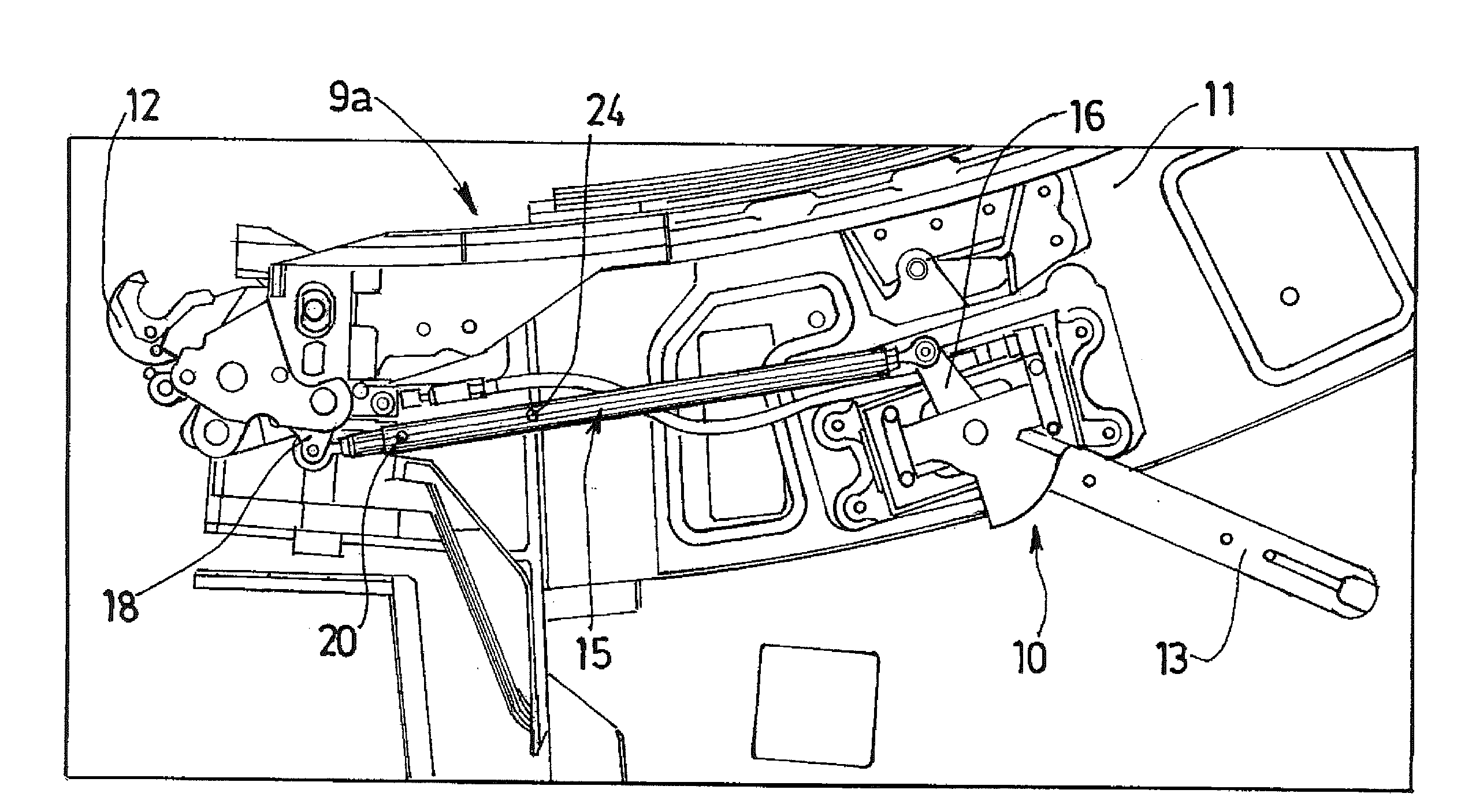
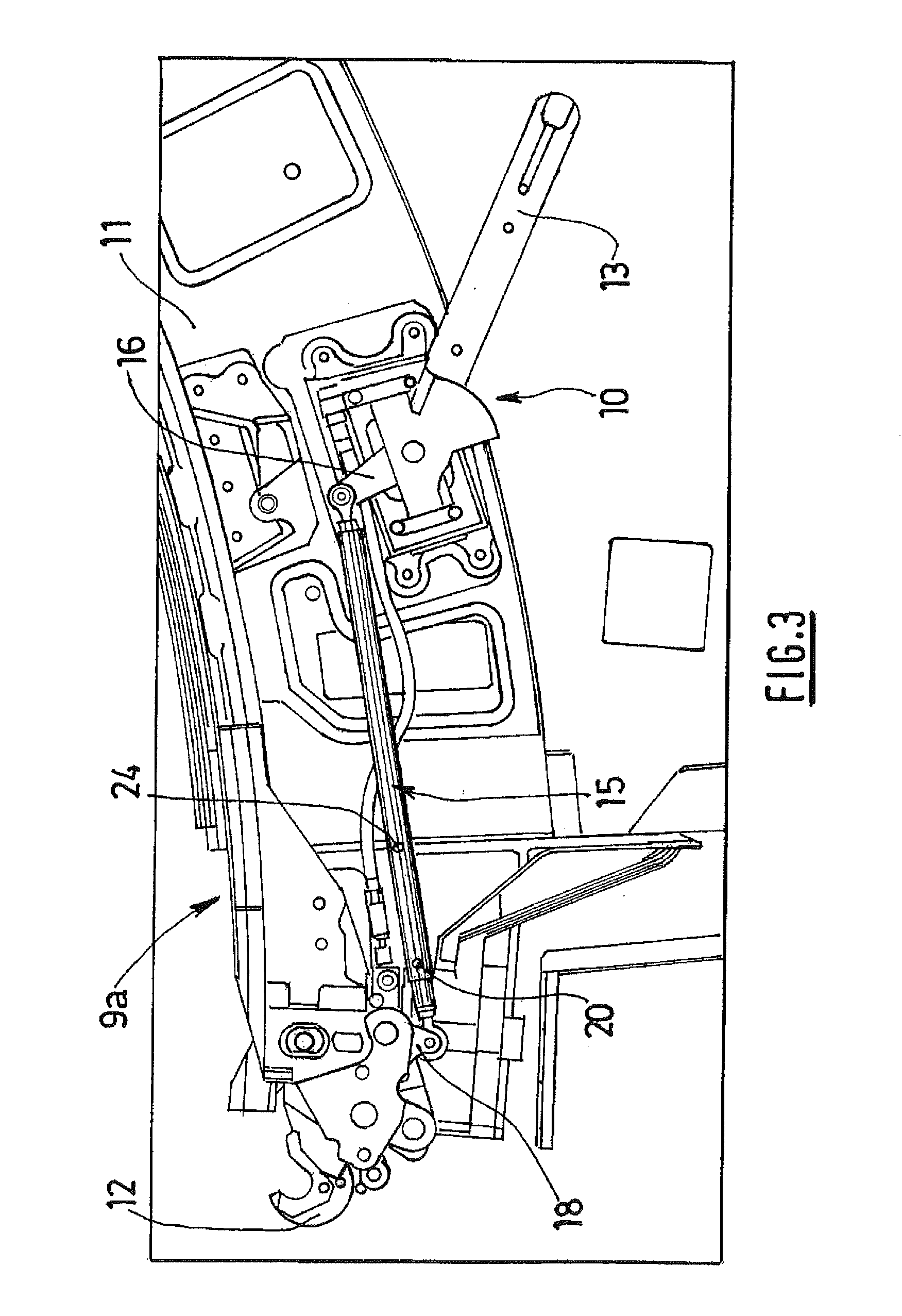
[0008]Thus, using a telescopic connecting rod combined with return means makes it possible to become compliant with regard to relative displacements between the locking member and the control handle. To be precise, the deflection allowed by the telescopic connecting rod makes it possible to compensate these relative displacements, and the return means ensure that the locking member is held permanently in the locked position on the complementary locking member during these relative displacements. Locking is therefore effective and secured, and the telescopic connecting rod is subjected to only very low mechanical stress.
[0009]Moreover, the operators are no longer forced to carry out an extremely precise setting of the transmission means on account of the deflection allowed by the telescopic connecting rod. This therefore affords a considerable advantage, as compared with the conventional locking devices which prevent any approximation because of their rigidity.
[0017]Another advantage is therefore that, if the stresses exerted on the control handle for the purpose of closing it cease before the latter reaches its closed and secure position, the stressing member tends to return it into its opening position. Consequently, it is easier to detect the improper closing of the locking device visually.
[0019]A very important advantage, then, is that the return of the control handle toward its opening position by virtue of the return member in the event of a cessation of the closing stresses during the intermediate phase thereby makes it possible to prevent the closing and locking of the fan cowl arranged around it.

Problems solved by technology

Moreover, the operators are no longer forced to carry out an extremely precise setting of the transmission means on account of the deflection allowed by the telescopic connecting rod.

Method used


Image

  • Locking device comprising a telescopic connecting rod equipped with return means
  • Locking device comprising a telescopic connecting rod equipped with return means
  • Locking device comprising a telescopic connecting rod equipped with return means

Examples


Embodiment Construction

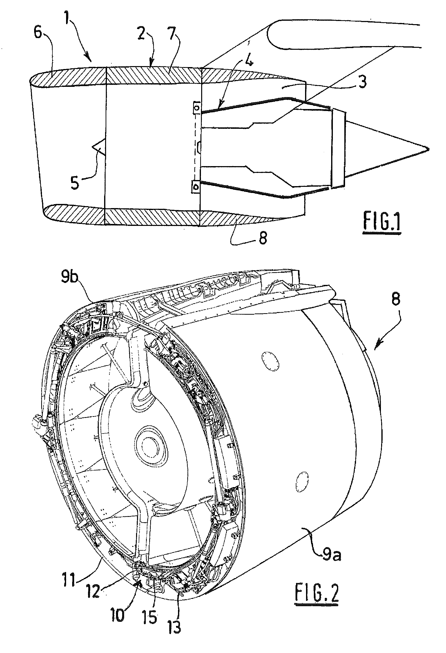
[0028]An aircraft nacelle 1 according to the invention, as illustrated in FIG. 1, comprises in a way known per se an external structure 2, called an OFS, which defines an annular flow channel 3 with a concentric internal structure 4 surrounding the actual structure of the turbojet engine (not illustrated) at the rear of a blower 5.

[0029]More specifically, this external structure 2 is broken down into a front air inlet section 6, a middle section 7 intended for surrounding the blower 5, and a rear section 8 formed from at least two half-shells 9a, 9b.

[0030]In the operating position, the two half-shells 9a, 9b are positioned nearest to the turbojet engine and are conventionally held in this position with the aid of a plurality of locking devices provided along a junction line located in the lower part (at 6 o'clock).

[0031]As illustrated in FIG. 2, a locking device 10 according to the invention may, in particular, be integrated in the front part of the rear section 8, and more especia...


PUM


Abstract

The present invention relates to a locking device (10) designed to fixedly attach a first element (9a) to a second element, comprising a locking member (12) intended to equip the first element, an additional locking element intended to equip the second element, and a control handle (13) connected to the locking member via transmission means, characterized in that the transmission means comprise a telescopic connecting rod (15) designed to oscillate freely between a minimum extension position and a maximum extension position, and means for returning the telescopic connecting rod to its position of maximum extension, said return means being placed in a prestressed state when the control handle is in the closure position.

Description

TECHNICAL FIELD[0001]The present invention relates to a locking device designed for fixedly attaching a first element to a second element and, more particularly, to a turbojet engine nacelle equipped with at least one such locking device.BACKGROUND[0002]In order to lock two elements to one another, it has been known for a very long time to install a locking member in the first element and a complementary locking member in the second element and to control the attachment or detachment of these by means of a control handle connected to the locking member by transmission means, for example of the cable or rigid bar type.[0003]Within the specific scope of a turbojet engine nacelle comprising a front air inlet section, a middle section intended for surrounding a blower of the turbojet engine, and a rear section formed from at least two half-shells, these are conventionally held in the closing position by means of such locking devices arranged along a junction line located in the lower pa...

Claims


Application Information

Patent Timeline
Patent Type & Authority Applications(United States)
IPC IPC(8): F02C7/20F16C11/04
CPCB64D29/06E05B15/004Y10T403/59E05C3/30E05C19/145E05B15/0053
Inventor PROVOST, FABRICE
Owner SAFRAN NACELLES
Learn More