
Dental Wedge

Inactive Publication Date: 2011-07-14
CLARK DAVID J
View PDF11 Cites 22 Cited by
  • Summary
  • Abstract
  • Description
  • Claims
  • Application Information

AI Technical Summary

Benefits of technology

[0027]Among other things, a dental wedge according to the invention has the following features and / or advantages.
[0030]A dental wedge according to the invention is a two part translucent / opaque wedge to both allow lateral transmission of light energy and then to eventually reflect the light, once the wedge portion engaging the tooth has extended beyond (below or in the gingival direction) of the termination or gingival margin of the filling; where it will block the travel of the unused photons, then luminesce (glow) to essentially reflect the light back toward the filling instead of wasting the photon light energy that is radiating in the gingival direction.
[0039]A dental wedge according to the invention has a collapsing tip to avoid trauma or skewering of papilla.
[0040]A dental wedge according to the invention has a safe blunted tip to protect operator's finger from puncture wound and cross infection and to protect the patient's gingiva from being skewered.
[0045]A dental wedge according to the invention has a land area that is triangular or equivalent to not interfere with a separator ring shape such that it fits a separator ring. The back of the handle is too far away to be a problem however the land area is close enough to the filling / tooth area so a complimentary triangular shape is advantageous.
[0046]A dental wedge according to the invention has a convexity (in top view) in mid wedge varying from slight to abrupt and in varying lengths, some at base only, some at top only and some with continuous convexity from top to bottom (of this middle [in top view] area) that is designed to approximate the mid tooth concavity present in some teeth. It is therefore an advantage to have a wedge that has a mid tooth convexity to properly adapt and seal the matrix where the tooth often has a corresponding concavity.

Problems solved by technology

Because the new composite dental filling materials are more delicate than silver amalgam and cannot be packed as aggressively, it is common today to see that many posterior and anterior composite fillings have poor contacts that allow food impaction, etc.
The ensuing “Black Triangle” can further compromise the interproximal health with plaque accumulation and food impaction along with esthetic compromise, as the dark spaces between teeth are considered to be unaesthetic and prematurely ages the smile.
Some dental wedges, such as that shown in U.S. Pat. No. 7,223,101, along with others, have a slightly concave gingival surface that does not nearly address the problem of the wedge “riding up” into the embrasure space resulting in the above mentioned concavity in the resultant filling shape and or black triangle issue, as the arc is x angle or may be 5% hollow.
The very slight gingival concavity, is so minimal that it does little to allow the wedge to seat itself deeply into the gum area and therefore does not address the aforementioned problems that occur in some clinical situations such as deeper decay or hypertrophic gums (oversized interdental gum triangle).
First, the wedge's design is so flimsy that it does not create enough pressure to separate the teeth and is therefore marketed with the separate V3 and V ring separators.
The disadvantage with this system is that the wedge cannot be used alone; necessitating the additional time required to place the separating ring in addition to placing the wedge.
This becomes a more serious problem for the anterior teeth where the separating rings are typically not used because the shape of the front teeth is different than the posterior teeth.
The second problem with the wedge of US 2007 / 0254263 is that the top angle or corner is pointed which can put unfavorable pressure on the matrix and create a flat spot on the matrix and the resultant filling shape.
The third problem is that the wedge of US 2007 / 0254263 is opaque, not allowing light transmission.
The fourth problem is that the wedge of US 2007 / 0254263 along with most other wedges must be inserted from one side of the teeth or the other side, and that to be thin enough to pass through the narrow space disallows a wide and broad pressure to adequately press the matrix against the tooth in the outer curved area.
Another problem is that of translucency to allow the photons of the curing light to reach the composite material to initiate and complete the photopolymerization.
Furthermore, traditional dental wedges have historically had a poorly designed grip area.
Worsening the problem of the poorly designed end of the wedge is that all plastic wedges to date have a vestige on the outer end surface that disadvantages the dentist further encouraging the back or handle end of the pliers to slip off the outer end surface and traumatize the gums or tooth in addition to requiring the dentist to waste time and energy.
This is referred to as an overhang or excess of filling material and often results in chronically inflamed gum tissues and potential gum disease and aggravation to patient as the floss shreds and snags.

Method used


Image

  • Dental Wedge
  • Dental Wedge
  • Dental Wedge

Examples


first embodiment

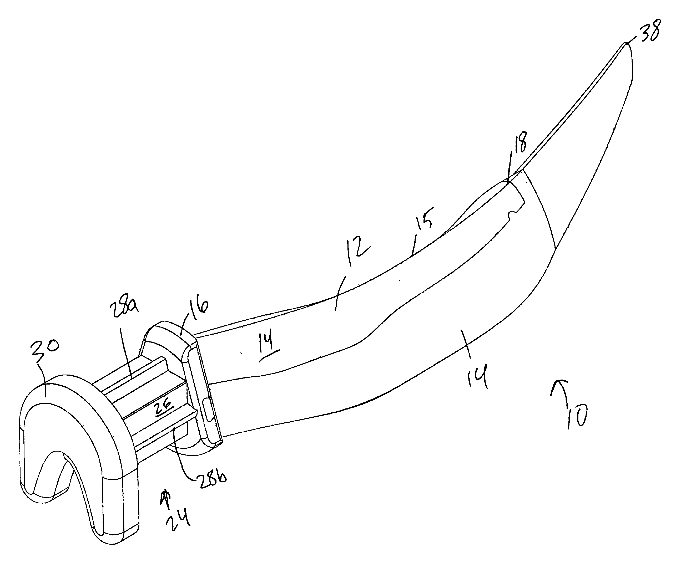
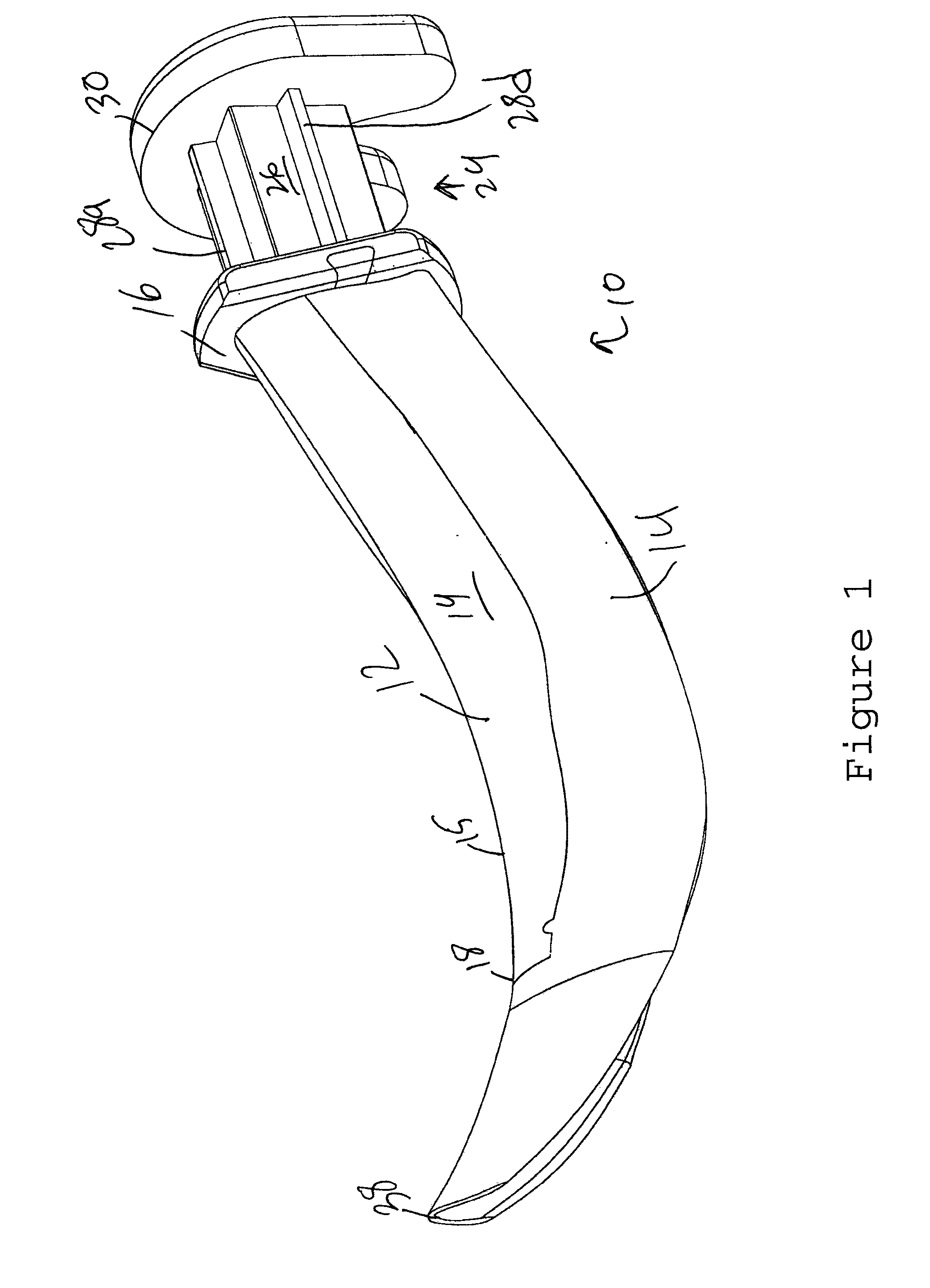
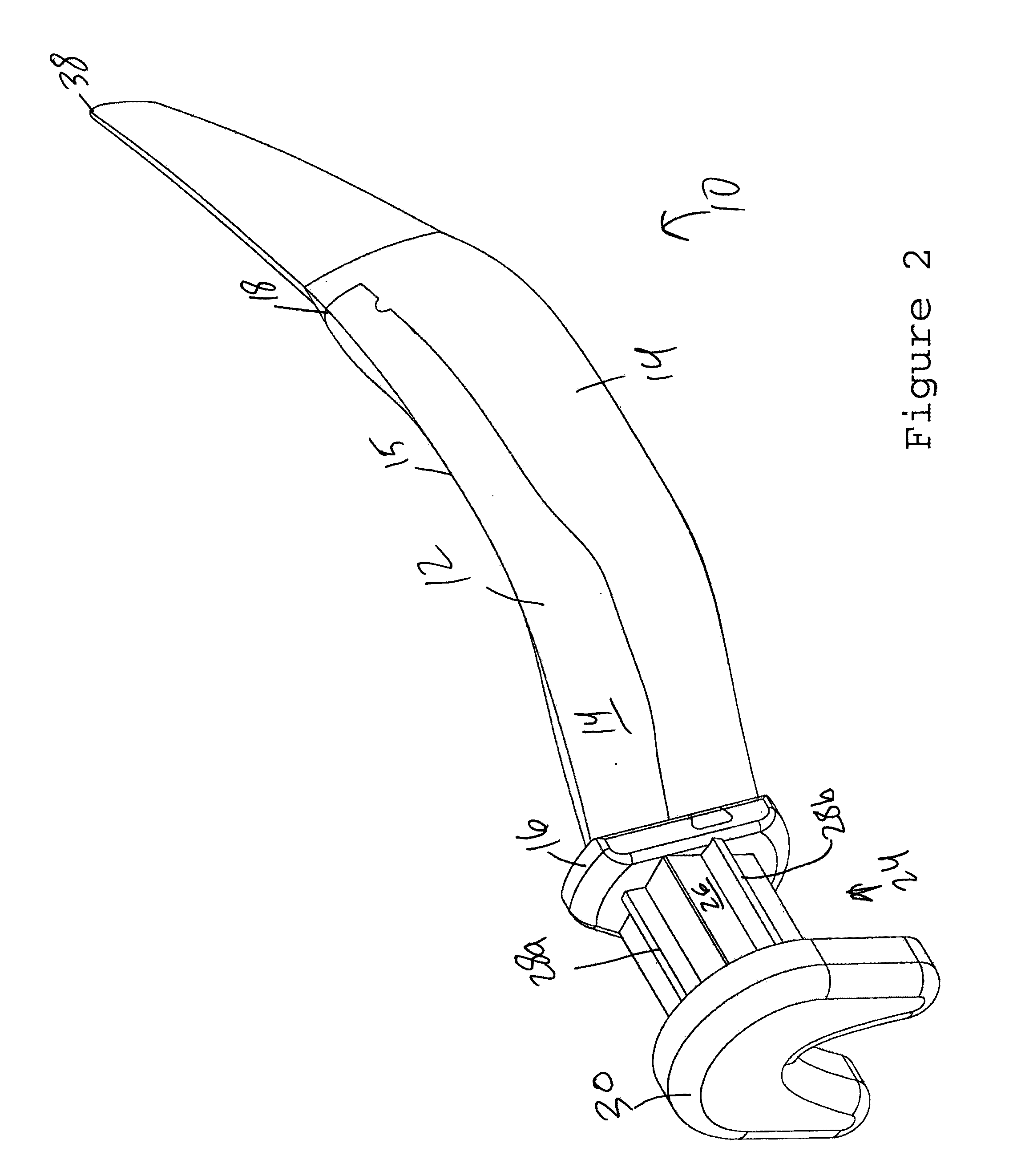
[0116]Turning to FIGS. 1 to 16, a dental wedge 10 according to the invention is shown. The dental wedge 10 includes a top section 12 and a bottom section 14. The use of relative terms such as “top”, “bottom”, “front”, “rear”, “inner”, “left”, “outer”, “right”, and the like when describing the dental wedges of the invention is not intended to limit the orientation in which the dental wedge 10 may be used. Such relative terms merely serve to more conveniently describe the invention. Unless the context clearly indicates the contrary, “top” will refer to the direction toward the closed end of the dental wedge, “bottom” will refer to the direction toward the open end of the dental wedge, “inner” or “left” will refer to the direction toward the end of the dental wedge that is first inserted between adjacent teeth, “outer” or “right” will refer to the direction toward the end of the dental wedge that is grasped when the dental wedge is inserted between adjacent teeth, “front” will refer to...

second embodiment

[0132]Turning to FIGS. 17 to 24, a dental wedge 110 according to the invention is shown. The dental wedge 110 includes a top section 112 and a bottom section 114. The use of relative terms such as “top”, “bottom”, “front”, “rear”, “inner”, “left”, “outer”, “right”, and the like when describing the dental wedge 110 of the invention is not intended to limit the orientation in which the dental wedge 110 may be used as explained above.

[0133]The top section 112 has a generally arcuate top surface 119 and a rounded top edge 115 that extends from a first vertical land area 116 to a paper thin (e.g., 0.001″-0.050″) collapsing distal tip 138 that is inward from the end of the wedge 110. Extending away from the vertical land area 116 opposite the tip 138 is a first grasping section 124 having a base 126 and splines 128a, 128b, 128c and 128d that extend outwardly from the base 126. The splines 128a, 128b, 128c and 128d are generally plate-like but can also have other shapes. Extending away fro...

third embodiment

[0138]Turning to FIGS. 25-31, a dental wedge 310 according to the invention is shown. The dental wedge 310 includes a top section 312 and a bottom section 314. The use of relative terms such as “top”, “bottom”, “front”, “rear”, “inner”, “left”, “outer”, “right”, and the like when describing the dental wedge 310 is not intended to limit the orientation in which the dental wedge 310 may be used as explained above.

[0139]The top section 312 has a generally arcuate top surface 319 and a rounded top edge 315 that extends from a first vertical land area 316 to an end 318 that is inward from the end of the wedge 310. The top section 312 has a central longitudinal body 320 that extends from the land area 316 to the end 318. The body 320 is located below the top surface 319. Extending away from the first vertical land area 316 opposite the end 318 is a first grasping section 324 having a base 326 and splines 328a, 328b, 328c and 328d that extend outwardly from the base 326. The splines 328a, ...


PUM


Abstract

The present invention relates to dental wedges that may be used for creating space between adjacent teeth. In one form, the dental wedge includes an elongated body extending from an outer end to an opposite inner end. The body has a longitudinal intermediate wall, a longitudinal first side wall connected to the intermediate wall, and a longitudinal second side wall connected to the intermediate wall. The first side wall and the second side wall each flare away from the intermediate wall such that a first distal end of the first side wall and a second distal end of the second side wall are spaced apart creating an inverted generally V-shaped transverse section for the body. The body has a top surface formed by the intermediate wall, the first side wall and the second side wall. The body also has a bottom surface formed by the intermediate wall, the first side wall and the second side wall. The dental wedge includes a grasping section connected to the outer end of the body. A hollow region is defined by the bottom surface of the wedge and a first reference line extending from the first distal end of the first side wall to the second distal end of the second side wall. At least a first portion of the body comprises a first material that transmits light.

Description

CROSS-REFERENCES TO RELATED APPLICATIONS[0001]This application claims priority from U.S. patent application No. 61 / 295,070 filed Jan. 14, 2010.STATEMENT REGARDING FEDERALLY SPONSORED RESEARCH[0002]Not Applicable.BACKGROUND OF THE INVENTION[0003]1. Field of the Invention[0004]The present invention relates to dental wedges that may be used in the restoration of a decayed portion of a tooth.[0005]2. Description of the Related Art[0006]Dental cavities that have spread to the dentin or have undergone cavitation are typically treated by removing the decayed portion of the tooth and thereafter filling the missing tooth structure with a restorative material such as silver (amalgam), white (resin), porcelain, or gold. Cavities that are located adjacent to neighboring teeth are called interproximal cavities.[0007]When treating interproximal cavities, the dentist first removes the decayed portion of the side of the tooth. In order to properly deposit the restorative material on the side of the...

Claims


Application Information

Patent Timeline
IPC IPC(8): A61C3/00
CPCA61C5/127A61C5/88
Inventor CLARK, DAVID J.
Owner CLARK DAVID J
Features
  • Generate Ideas
  • Intellectual Property
  • Life Sciences
  • Materials
  • Tech Scout
  • Unparalleled Data Quality
  • Higher Quality Content
  • 60% Fewer Hallucinations
Learn More