Mixer

A kneading machine and kneading technology, which is applied in the direction of mixers, mechanical equipment, mixers with rotating stirring devices, etc., can solve the problems that the kneader cannot maintain the sealed state

Active Publication Date: 2015-03-18
MITSUBISHI HEAVY IND MACHINERY SYST LTD
View PDF2 Cites 2 Cited by
  • Summary
  • Abstract
  • Description
  • Claims
  • Application Information

AI Technical Summary

Problems solved by technology

[0011] However, the above-mentioned displacement information of the sealing device described in Patent Document 1 is to confirm whether it is necessary to inspect the sealing device or replace parts. Although the sealing state can be grasped through this information, it cannot maintain proper sealing during the operation of the kneader. state

Method used


Image

  • Mixer
  • Mixer

Examples


Embodiment Construction

[0038] Next, the kneader 1 according to the embodiment of the present invention will be described.

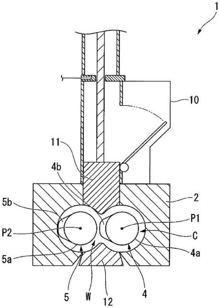
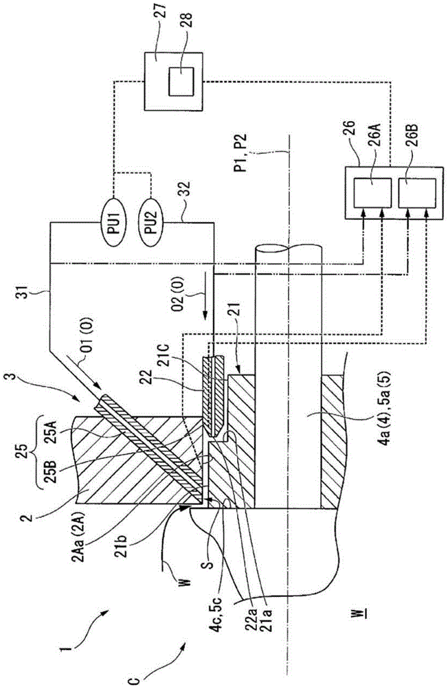
[0039] Such as figure 1 As shown, the kneading machine 1 has: a chamber 2 with a space formed inside, a pair of kneading rotors 4, 5 arranged in this space, and a pair of kneading rotors 4, 5 between the kneading rotors 4, 5 and the chamber 2 Sealing device 3 for sealing the gap (refer to figure 2 ), is the so-called closed mixer.

[0040] The chamber 2 is a member having a space formed therein. And this internal space is a kneading chamber C which kneads the kneaded material W, such as a rubber raw material.

[0041] The upper part of the chamber 2 is provided with a hopper 10 for inputting the kneading material W and a floating weight 11 that can move up and down, and the kneading material W input from the hopper 10 is pressed into the kneading chamber by the descending action of the floating weight 11 C inside.

[0042] Furthermore, a discharge door 12 for opening the ...


PUM


Abstract

This mixer is provided with: a chamber (2) in which a mixing chamber (C) is formed for housing a mixing material (W); a mixing rotor (4(5)) which is arranged to pass through the chamber (2) and which stirs the mixing material (W) inside of the mixing chamber (C) by rotating about an axis line (P1(P2)); a seal member (22) which seals the space between the chamber (2) and the mixing rotor (4(5)); a lubricating oil supply unit (25) which supplies a lubricating oil to between the chamber (2) and the mixing rotor (4(5)); a detection unit (26) which detects a state quantity which varies with the state of sealing between the chamber (2) and the mixing rotor (4(5)); and a control unit (27) which controls the amount of lubricating oil (O) supplied from the lubricating oil supply unit (25) on the basis of the result of detection in the detection unit (26).

Description

technical field [0001] The invention relates to a kneader for stirring kneaded materials such as rubber raw materials. [0002] This application claims priority based on Japanese Patent Application No. 2013-021716 for which it applied to Japan on February 6, 2013, and uses the content here. Background technique [0003] There is known a closed type kneader that agitates a kneaded product made of rubber, plastic, etc. that is pressed into a kneading chamber by rotation of a rotor shaft. In this closed kneader, a sealing device is provided to prevent the kneaded material from leaking from the gap between the rotor shaft and the kneading chamber. The sealing device supplies lubricating oil to the sliding portion so that the rotor shaft maintains a good sliding state when it rotates. [0004] However, in this type of sealing device, the components of the sealing device are worn due to the operation of the kneader, and the sealing state (leakage state and sliding state of the k...

Claims


Application Information

Patent Timeline
Patent Type & Authority Applications(China)
IPC IPC(8): B29B7/18B01F7/02B01F15/00B29B7/22
CPCB29B7/22B29B7/246F16J15/3296F16J15/162F16J15/406B29B7/183B29B7/7495B29B7/242B29B7/283B29B7/94B29B7/28
Inventor 森部高司吾川二郎山下顺弘花田修一高桥和仁
Owner MITSUBISHI HEAVY IND MACHINERY SYST LTD
Why Eureka
Try Eureka